
Green hydrogen production via water electrolysis is already moving beyond the laboratory. Large-scale hydrogen projects based on alkaline water electrolysis (AWE) and proton exchange membrane water electrolysis (PEMWE) technologies are being deployed at megawatt, even gigawatt scale, and the technology is steadily maturing.
Despite this progress, these mature technologies are not without drawbacks such as load flexibility, cost and durability. This has led to growing interest in anion exchange membrane water electrolysis (AEMWE) as a next-generation alternative. AEMWE systems combine advantages of both established technologies. Like PEMEL, they offer the operational flexibility needed to integrate intermittent renewable energy sources. At the same time, their alkaline operating environment allows the use of cheaper, earth-abundant materials, similar to conventional AWE.
However, AEMWE is still at an earlier stage of development. In particular, achieving both high performance and long-term stability with current electrode designs remains a major challenge.
Inside the electrode
Inside an electrolyser, electrodes are where water splits and evolves into H2 and O2. Current state-of-the-art electrodes are composed of an electrically conductive porous transport layer (PTL), oftentimes nickel mesh, that facilitates water, gas, and electron transport, and a thin layer of catalyst particles attached to the PTL or membrane using an ion conducting ionomer. This ionomer is a polymer that is able to transport ions between the catalyst while also serving as a glue, so that catalyst particles stay intact without falling out and leaving the electrolyser system.
This multi-component, layered architecture in electrodes require several manufacturing steps, including synthesis of catalyst nanoparticles, catalyst ink formulation, and spray or decal deposition onto the supporting surface (Figure 1). This keeps the electrode manufacturing complexity and cost high, which takes a significant portion of the electrolyser stack CAPEX. (IRENA 2020)
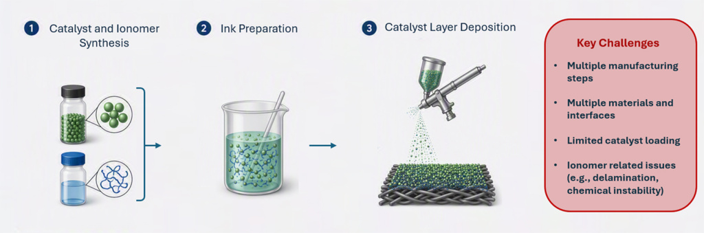
When it comes to AEMEL electrodes, there comes performance issue on top of the aforementioned complex manufacturing issue. While the earth abundant transition metals enable low raw material cost, their intrinsic performance is far less than that of noble metals and therefore require extensive chemical modifications and higher loading. Moreover, the immaturity of anion exchange ionomer science also poses complications such as electrocatalyst layer delamination that negatively influences stability of the electrolyser performance.
Despite the difficult situation, the research goals and market demand remain ambitious. New electrode designs must therefore address manufacturing complexity, cost, performance, and stability simultaneously.
Balancing quality with quantity
How can a less active catalyst compete with a highly active one? One solution could be to balance quality with quantity. Device performance is not only determined by how active each individual site is but also depends on how many sites are available and accessible.
Does that mean we simply add more catalyst? In practice, adding more material does not necessarily improve performance. Packing catalyst particles into a dense layer often results in poor utilisation, as many active sites become inaccessible due to limitations in transport of reactants and products. This raises an important question: how can we increase the number of accessible active sites without creating a thick, dense, and less efficient catalyst layer? One possible approach is to make better use of the PTL that is already present within the electrode architecture.
Maximizing performance while minimizing cell components
In AEMEL, the PTL is metal mesh typically made from nickel microfibers woven or stacked together. It provides mechanical support for the catalyst layer and transport pathways for water, gas, and ions. Although nickel can serve as catalyst for water splitting, conventional PTLs contribute little to cell performance because their surface area is too low. We therefore hypothesized that dramatically increasing the PTL surface area could enable the PTL itself to serve as both catalyst and transport medium, removing the need for a separate catalyst layer.
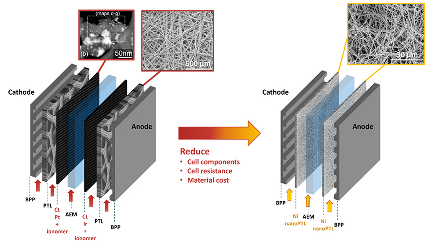
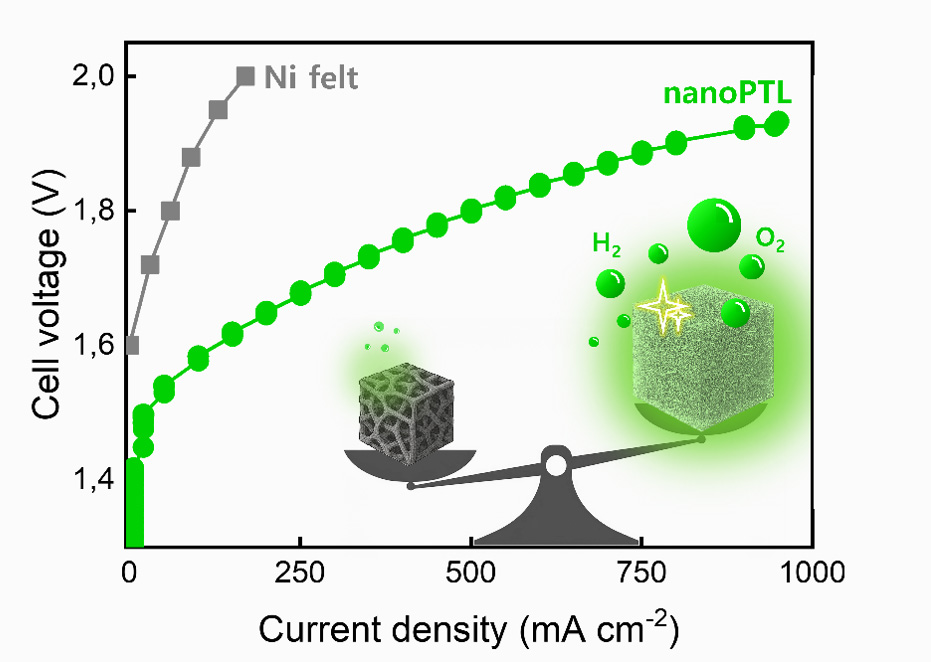
To test this hypothesis, nanoPTL was developed by reducing the nickel fibre thickness from the microscale to the nanoscale (Figure 2). The nickel fibre thickness in nanoPTL was reduced by approximately 500 times compared to the commercial nickel felt. It demonstrated that the nanoPTL alone could serve as both active catalyst and transport medium for AEMEL (Figure 3). More importantly, nanoPTL is self-standing and does not require any binder to maintain its structure. As a result, the ionomer is no longer needed as an adhesive component. This integration of two functions into a single component can reduce cell complexity and lower material and manufacturing costs. Fewer components and interfaces can also reduce interfacial resistance, improving overall device efficiency.
From concept to ongoing research
SINTEF Industry is currently actively developing this concept in collaborative EU projects AMELIA and SWEETHY. In both projects, our main focus is on tuning intrinsic activity of nanoPTL by doping and surface modifications, aiming for low cost, high performance, and stable AEM electrolysers.
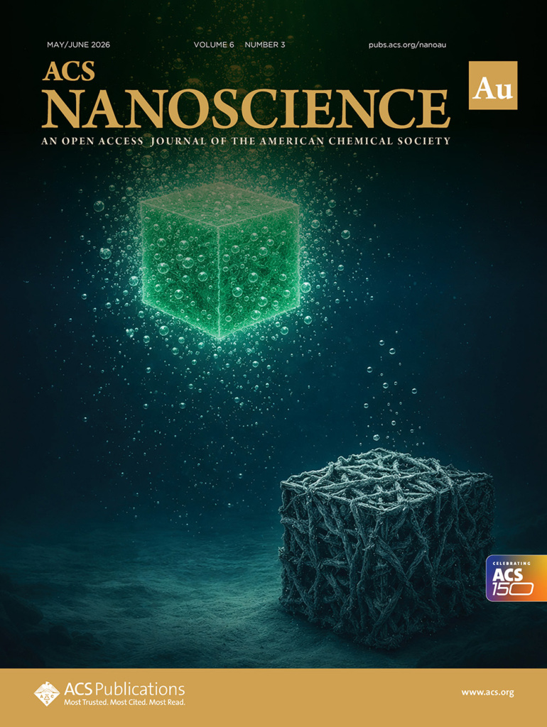
The nanoPTL was first validated in AEMWE single cell level at the Norwegian Fuel Cell and Hydrogen Centre as proof of concept and the outcome was published in a recent journal paper (ACS Nanoscience Au). The article was selected as the front cover for the next journal issue (Figure 4).
Development is continuing, with focus on improving performance under more realistic operating conditions, understanding degradation mechanisms over time, and scaling up the nanoPTLs manufacturing process.
A different way forward
Established technologies are often advanced by optimizing existing components. At SINTEF, we took a different perspective. Instead of asking how to improve the catalyst layer, we asked whether the catalyst layer could be eliminated altogether.
By integrating multiple functions into a single component, reducing manufacturing complexity, and enabling the use of abundant materials, it becomes possible to address performance, cost, and sustainability simultaneously. For green hydrogen to scale globally, such approaches may offer an alternative path forward.
This concept, known as self-standing electrodes, has recently been recognized by the European Commission’s Innovation Radar within the AEMELIA project, together with Tecnalia as a collaborating research organisation.
View the full publication:
Choi, Y., et al. (2026). Toward simplified electrode design: Development of nickel-efficient catalytic nanoPTL for sustainable AEM water electrolysis. ACS Nanoscience Au. Advance online publication. https://doi.org/10.1021/acsnanoscienceau.5c00168





















Comments
No comments yet. Be the first to comment!