


For certain types of designs, a higher voltage comes with an increased risk of water trees, a phenomenon that can lead to failure and very expensive repairs. But what makes water trees appear in some places on a cable and not in others? This is one of the questions the Ocean Grid Research on high voltage (HV) inter-array subsea cables is trying to answer.
Background
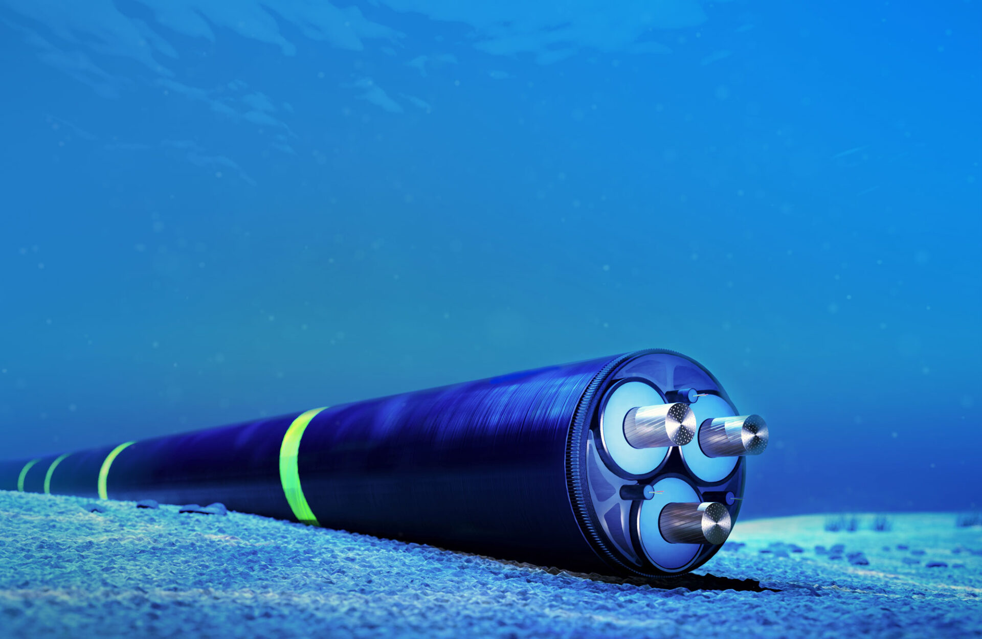
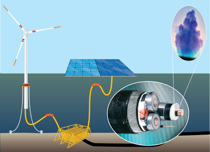
Inter-array cables connect offshore wind turbines to the electrical grid through offshore substations. The key components of such cables are the conductor core, typically copper, and the insulation system. The insulation system consists of cross-linked polyethylene (XLPE) and inner and outer semi-conductive screens. For cable ratings up to 36 kV there are no outer metallic layers protecting the insulation system from water, and this design is therefore referred to as “wet-design”. High voltage cables rated from 52 kV and above are normally equipped with a metallic layer consisting of an extruded lead sheath, preventing water from migrating into the insulation.
However, there are several drawbacks related to the use of lead sheaths. These include environmental issues, additional weight and cost (both production cost and installation cost), and poor dynamic mechanical properties. As more offshore wind turbines are becoming floating installations, the dynamic performance of a cable is increasingly important. Therefore, it could be advantageous remove this lead sheath also for cables above 52 kV.
Water treeing
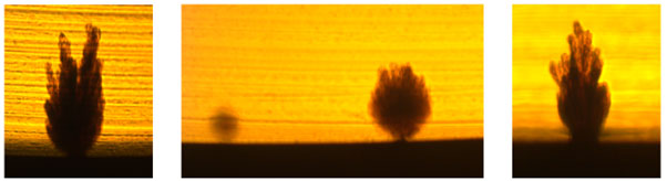
The main challenge preventing the use of wet-design HV subsea cables is water treeing. To initiate vented water treeing, a contamination or microstructural defect is required at the interface between the insulation and semi-conductive screen. This has been observed in MV cables for a long time, but with significant improvements in the raw materials, production and processing, the extent of water treeing was strongly reduced. Until recently, water treeing has not been an issue for high voltage cables as they have normally been designed “dry” due to the outer water impervious extruded lead sheath. Recent results show that vented water trees in high voltage cables are typically not growing from a contaminant positioned at the interface between the insulation screen and the cable insulation, but from a perfectly smooth interface. How can that be?
Our investigation
o investigate the water trees and their surrounding area even closer than before, we have used a combination of low vacuum scanning electron microscopy (LV-SEM) and scanning transmission electron microscopy with energy dispersive X-ray spectroscopy (STEM-EDS) to perform microstructural and chemical analyses.
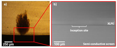
The water tree inception site was first analyzed by LV-SEM. The analysis confirmed that the interface between the XLPE insulation and the semi-conductive screen was smooth, and there were no anomalies in the microstructure indicating why the water tree initiated at this exact position. A chemical analysis of the same area was therefore performed by STEM-EDS, where the resolution is even higher.
Simply put, we cut a thin slice through the middle of the water tree presented in Figure 3a. The STEM-EDS analysis, just as the LV-SEM, confirmed a smooth interface and a homogeneous microstructure across the sample. However, there were two exceptions, and these are the ones presented in Figure 4 and 5.
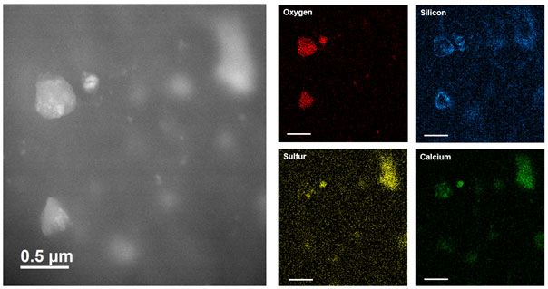
The STEM image in Figure 4 shows that inorganic impurities are present in the water tree region of the XLPE insulation. By EDS analysis these impurities were identified as oxygen, silicon, sulfur, and calcium. The silicon appears like a shell-like structure with oxygen, sulfur and/or calcium inside, suggesting the presence of the compounds CaSO4, CaS, and SiO2 along with Si-O bonded to the polymer.
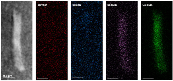
In Figure 5, the STEM image shows a macroscopic particle in the semi-conductive screen, positioned right below the inception site of the water tree. Chemical mapping of this area by EDS shows how the particle consists of sodium and calcium, while oxygen and silicon are evenly distributed over the entire area.
This study shows that the impurity concentration in modern HV subsea cables is already very low. The impurities that are present can originate from various sources during processing and handling, as well as the surrounding environment. Several of the impurities detected in this work has previously been related to water treeing in MV subsea power cables. If it turns out they are now initiating water trees in HV cables, despite their very low concentration, it will be important to determine their origin.
Are the impurities causing water trees?
Without the water protective lead barrier, water trees grow in significant numbers and lengths in modern HV XLPE subsea power cables. Even though no contaminations or defects are observed at the smooth interface where the water trees initiate, we saw by STEM-EDS that inorganic impurities are present both in the water tree and directly below its inception site. Moving forward it will therefore be interesting to see if the same elements appear where there are no water trees, indicating if these can be directly related to the water treeing.


Comments
Dear Sofie Brandtzæg Hårberg,
I just came along with your contribution to the SINTEFblog on water trees. I did my Ph.D. thesis on this topic under Prof. Rainer Patsch (Uni. Siegen, Germany), and I would like to know if you have already found new insights into the causes of watertree development.
Kind regards,
Pedro A. Romero Rojas
Dear Pedro,
Since this contribution was posted on the SINTEFblog, we have found new structures within the semi-conductive screens that we believe are crucial for the premature ageing through water treeing. Large voids containing sodium chloride are observed in the screens, and porous regions/paths containing salts are observed going from these voids to the water tree inception site.
If you are interested in more details, we published a paper on this earlier this year: https://doi.org/10.1002/app.56136
Kind regards,
Sofie Brandtzæg Hårberg