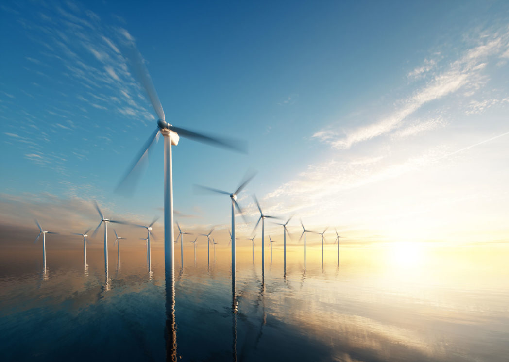
Offshore wind farms are being commissioned at an ever-increasing rate and are expected to play a significant role in supplying energy to Europe in the future.
In general, offshore wind farms produce more energy than onshore installations due to better wind conditions and fewer constraints on the number of turbines and their physical dimensions.
However, the process of exporting energy from wind farms located far offshore remains a major challenge.
- Find out more about SINTEFs expertise on HVDC transmission.
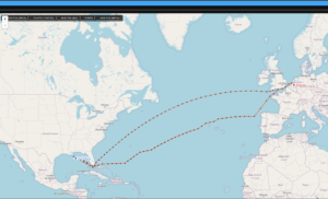
- The technology and lab facilities are also very relevant for development of transnational power transmission, in which Statnett is strongly engaged, with HVDC links to Germany and Uk under Construction.
Interconnected HVDC offers more reliable power export
High Voltage Direct Current (HVDC) transmission using DC submarine cables is the most efficient and cost-effective technology available for the transfer of bulk power over long distances.
The classical cable export configuration is referred to as a point-to-point connection, involving the installation of an HVDC station on a platform offshore, and another on the mainland.
If the link fails, the energy generated cannot be exported, resulting in losses for the operators. Greater reliability can be achieved using multi-terminal HVDC topologies in which multiple HVDC stations are interlinked.
This offers the opportunity to reroute power transmission via alternative functioning links if one of the links fails.

We have built a laboratory demonstrator
As part pf the BestPaths project, we have built a laboratory-scale demonstrator of a multi-terminal HVDC transmission system and an offshore wind farm.
This demonstrator is quite unique in its capabilities, and is accessible to researchers and the industry as a testbed for their ideas and systems.
The offshore wind farm is reproduced using a real-time simulation model created by a wind turbine manufacturer. This was carried out at our National Smart Grid Laboratory, operated jointly by SINTEF Energy Research and the Norwegian University of Science and Technology.
The demonstrator makes it possible to examine complex configurations at smaller scales and predict potential interoperability issues related to the various components. The aim here is to reduce the risk linked to these new technologies in a controlled laboratory environment before implementing them at full-scale, where any problems arising would result in very high costs.
Find out more by watching this film.
Find out more about the BESTPATHS-project here.
This project has received funding from the European Union’s Seventh Programme for research, technological development and demonstration under grant agreement No 612748.


Comments
No comments yet. Be the first to comment!