
Are you interested in saving our climate by enabling large-scale Carbon Capture and Storage (CCS)? Then you are (believe it or not) also interested in advancing today’s well technology and well integrity. Why? Because wells are the “gatekeepers” of stored CO2! Their quality will determine for how long CO2 remains imprisoned in deep subsurface reservoirs.
What is a well?
It is common to visualize wells as just long tunnels into the ground whose sole purpose is to suck up oil and gas from subsurface reservoirs. The fact is, however, that these are complex engineering structures that require careful design – and they are important for so many other purposes than just extracting hydrocarbons. For starters, drilling a well is the only way to get up samples from the subsurface that scientists can study to learn more about our planet. Wells are also essential for exploiting geothermal energy – and (as you will see) for CO2 storage in the subsurface.
When drilling down into the ground, for whatever purpose, it will become increasingly hot and pressurized with depth. An oil/gas well can have temperatures and pressures similar to those obtained in a kitchen pressure boiler. Thus, the further you drill – the harder it becomes to stabilize the rock walls to avoid collapse. As a result, it is necessary to cement steel pipes into the borehole to “save progress” whenever a difficult rock interval has been pierced. Thus, a typical well ends up with a “telescopic” structure of cemented pipes of different diameters.
When the productive life of a well is over it will be necessary to plug it, since it can never be removed. This process typically involves pulling out sections of the steel pipes, and placing cement plugs (of about 100 m length) in two or three intervals of the well. The goal is then that this plugging procedure seals off the reservoir for eternity.
Wells in CO2 storage projects
When it comes to CO2 storage, wells are used for CO2 injection purposes and for producing reservoir fluids (to ensure that injection doesn’t increase the pressure too much). If CO2 is to be stored in a depleted hydrocarbon reservoir it must also be expected that a high number of plugged oil/gas wells perforate the site. If these are very old it is important to check the quality of plugging, since early methods for sealing wells involved filling them with tree stumps, logs, animal carcasses and mud.
In principle, all well types can cause leakage of CO2 – as they represent man-made punctuations of the natural reservoir seal. In fact, the Intergovernmental Panel on Climate Change (IPCC) write in their special report on CCS that: “injection wells and abandoned wells have been identified as one of the most probable leakage pathways for CO2 storage projects” (p. 244).
Contrary to what you might think – this IPCC conclusion is actually great news for all those hoping for large-scale CCS in the future. Why? Because leakage along wells is just so much easier to detect, avoid and mitigate than leakage through other potential pathways, e.g. geological faults. We typically know where the wells are, meaning that limited monitoring is needed to reveal leakage, and we have methods to repair them. The most cost-efficient option is, however, to construct wells in a robust manner to ensure that leakage does not become an issue.
Ongoing research in BIGCCS
Applying wells for large-scale CCS purposes represent a brand new challenge, and it is not given that just adopting well technology from the oil and gas industry will result in the most efficient CO2 wells. Scientific studies are needed to investigate how to build robust wells for CCS, how to operate them safely – and how to best repair them if they are damaged. This is the focus of the Well Integrity research team, that I am a part of, in BIGCCS.
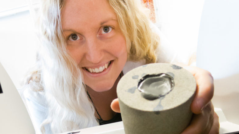
Through laboratory work and numerical simulations, the Well Integrity team exposes small-scale wells to severe CCS conditions. We then observe how they fail – and recommend strategies for how to avoid and repair such failure. Our team started the work in 2013, but we have already obtained some interesting results. We have mapped how various drilling muds affect cement bonding in CO2 wells, and we have studied numerically how temperature variations in the well can cause cement damage and subsequent leakage.
In the continuation of our work, we hope to accelerate the deployment of large-scale CCS by developing materials and methods for ensuring safe and cost-efficient CO2 well integrity.


Comments
No comments yet. Be the first to comment!