Skip to content

SINTEF Blog Gå til forsiden

  • Energy
  • Ocean
  • Digital
  • Health
  • Industry
  • Climate and environment
  • Building
  • Society
  • EN
  • NO
Energy

Safe CO2 transport pipes is part of the climate solution

CO2 capture, transport and sequestration.
authors
Svend Tollak Munkejord
Chief Scientist
Morten Hammer
Researcher
Stephane Dumoulin
Håkon Ottar Nordhagen
Gaute Gruben
Research Manager
Published: 27. Apr 2017 | Last edited: 15. Apr 2025
2 min. reading
Comments (4)

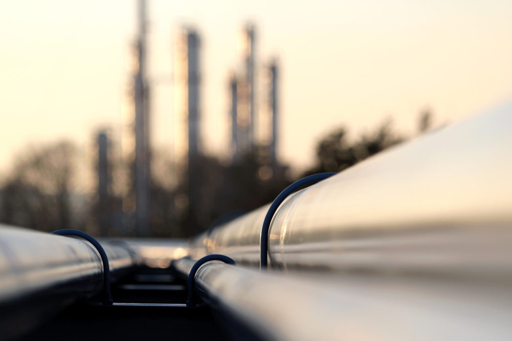
CO2 capture and storage (CCS) is an essential technology to mitigate climate change, as pointed out in the IPCC Fifth Assessment Report. To achieve this, large amounts of CO2 must be safely transported from the capture plants to the storage locations. Indeed, the amounts are comparable to today’s transport of natural gas.

  • Find out more about SINTEF’s expertise on CO2-transport

Since the CO2-transport system will be large, it is essential to make it as efficient as possible, while maintaining a high degree of safety.

This has been a subject of study in the BIGCCS Centre for environment-friendly energy research from 2009 to 2016. The work has been funded by the Research Council of Norway, and the industrial partners Engie, Gassco, Shell, Statoil and TOTAL.

Validation for CO2 and nitrogen

A main result of this work is an advanced coupled fluid-structure model able to predict whether a leak in a CO2-transport pipeline will form a long running-ductile fracture. The purpose of this model is to enable the design of pipelines where this will not happen – without overdesigning. Our latest findings have just been published in an article in the Engineering Structures journal.

(The article may also be read in the form of a preprint.)

The coupled fluid-structure model was validated against crack-arrest data for CO2 and for a CO2-nitrogen mixture from the COOLTRANS research programme in the UK – with good results. In addition, we presented a method to calibrate the material model when there is limited data available – which is often the case.


Aiming to develop an engineering tool for safe CO2 transport

It is our aim that our model may form the basis for developing an engineering tool that can aid the safe design and operation of CO2-transport pipelines and avoid long running-ductile fractures. This is also thought to be of interest for the Norwegian full-scale CCS project that is currently under development.

Related blogs

  • Understanding the forces at play when boiling CO2 drives a running pipeline fracture
  • CO2 transport – safety and efficiency requires quantification
  • Gas or liquid: new CO2 mixture property knowledge needed for efficient and robust CCS
  • Flow of CO2 in pipes
  • Why models are important for safe and efficient CO2 transport

Comments

No comments yet. Be the first to comment!

Leave a comment Cancel reply

Your email address will not be published. Required fields are marked *

More about Energy

How much can energy-efficient voyage planning save? Evidence from 11 months of North Atlantic data

Author Image
Author Image
2 forfattere
Infographic showing the flow of thermal energy storage (TES) from surplus heat or cold to end users. On the left, red and blue thermometer icons represent surplus heat and cooling, accompanied by the text “Surplus heat or cold – Captured and stored for when it’s needed.” In the centre, a large panel titled “Thermal Energy Storage (TES)” presents three storage technologies. The top section, “Sensible TES,” shows a container with a thermometer and the text “Stores heat in one single phase.” The middle section, “Latent TES,” shows a water droplet and snowflake connected by circular arrows, with the text “Stores heat through phase change.” The bottom section, “Thermochemical TES,” shows two connected coloured circles that separate and reconnect, illustrating a reversible reaction, with the text “Stores heat through reversible reactions.” A large pale arrow-shaped wedge points from the TES panel toward the right side of the figure. On the right, three application areas are shown in separate boxes with icons: industrial processes, buildings, and data centres. The layout conveys that surplus heat or cold can be stored using sensible, latent, or thermochemical TES technologies and later supplied to industrial facilities, buildings, and data centres.

Thermal energy storage is already commercial  

Jorge Salgado Beceiro
Research Manager

Burning ammonia cleanly: How timing changes everything 

Author Image
Author Image
2 forfattere

Technology for a better society

  • About this blog
  • How to write a science blog
  • Sign up for our newsletter
  • News from NTNU and SINTEF
  • Facebook
Gå til SINTEF.no
SINTEF logo
© 2026 SINTEF Foundation
Privacy Editorial Press contacts Website by Headspin