For instance, currently, the only pan-EEA/EU incentive for CCS is the emission trading scheme (ETS), where purchase of CO2 certificates under certain conditions are not needed for CO2 that is permanently stored in a geological reservoir. One of the conditions are traceable quantification of the amount of CO2 transferred from the source to the storage site. In addition, traceable flow measurements will most likely be needed for widespread transfer between different legal entities in the future CCS systems.
Challenges with fiscal metering
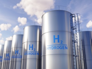
At the moment, it is not clear at the moment how traceable mass flow measurement will be achieved. CO2 will be transported in liquid or dense phase, in a state quite different from normal pipeline conditions of e.g. natural gas or a close to incompressible liquid like water. In addition, the high sound attenuation of CO2, and the fact that CO2 properties change quite a lot with varying pressure, temperature and impurity content, may make traceability to e.g. the standards of ETS challenging and will require development of specific procedures. So far, no traceable mass flow measurements have been demonstrated for flows at a scale relevant for CCS.
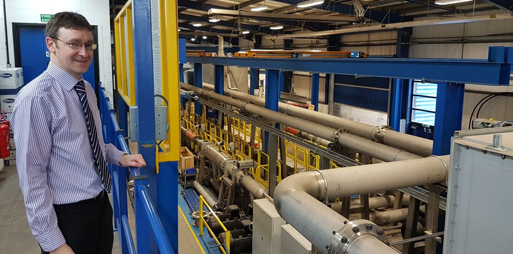
During calibration, tonnes of water are filled in the tank in the background. After a given time-period, the tank is weighed and the result compared with the reading of the flow meter under test.
SINTEF and KROHNE is working on it
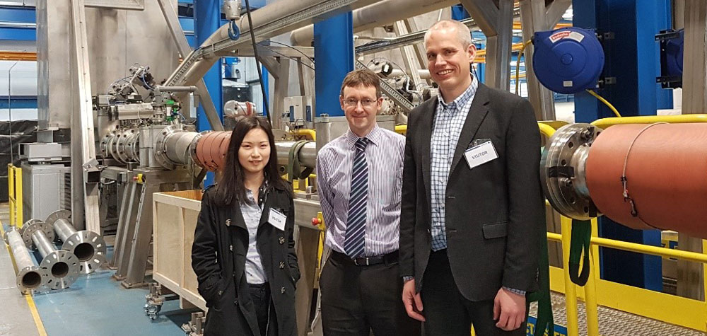
In NCCS Task 8, an activity is devoted to evaluation and benchmarking of candidate technologies for fiscal metering in CCS. KROHNE Ltd is an important partner of this work, and as a kick-start for the first benchmarking of fiscal metering technologies for CCS, scientists Han Deng and Sigurd W. Løvseth from SINTEF Energy Research recently visited KROHNE staff at their production plant and testing facility in Wellingborough outside London. Here, mass flow meters up to a pipe dimension of 400 mm and flow capacity of some thousand tonnes are tested routinely using water at multiple temperatures. This scale, and some of the methodology, will also be relevant for future verification of CO2 metering.


Comments
No comments yet. Be the first to comment!