
The research presented in this blog is a part of Centre for Environment-friendly Energy Research, BIGCCS.
In order to limit climate changes we need to cut CO2 emissions. The burning of fossil fuels for electricity and heat production is still the largest source of global CO2 emissions. Capturing the CO2 emissions from these processes will be important in order to reach the needed CO2 reduction. Chemical Looping Combustion (CLC) is a rather new and novel CO2 capture technology closely combining materials, reactor and combustion science. In BIGCCS we are doing research and development on this in order to bring CLC forward.
CLC belongs to the oxy-combustion route for CO2 capture. Fuel is burnt only with oxygen and not with air which is the normal when burning a fuel (e.g. as in your car engine, wood stove, gas burner etc.). The main benefit is that it produces an exhaust gas which consists mainly of CO2 and water vapour since no nitrogen is involved as would be the case with normal combustion in air. This makes the CO2 separation easy by just condensing out the water vapour.
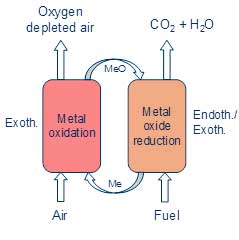
The clue in CLC is the way the oxygen is produced. The standard method for oxygen production is by cryogenic distillation of air at very low temperatures. CLC uses instead that metal particles can be rapidly oxidized in air at high temperatures, in the order of 850 – 1000°C. That is, the particles extract oxygen from the air. The resulting metal oxide particles are then transported to the fuel where the oxygen is released and used for burning the fuel. Thereafter they are transported back in order to continue the “looping” process as illustrated in the figure. This can be less energy intensive and costly than standard oxygen production methods.
The main challenges in CLC are development of suitable metal oxide particles as well as appropriate reactor and control systems for long time continuously operation. The metal particles must survive and do the job at high temperatures, they should ideally extract and release as much oxygen as possible in as short time as possible (some seconds) and they should not break down into fine powder, or agglomerate and clog into larger particles. The reactor and control system must ensure stable operation, high circulation of particles and full burn-out of fuel.
In BIGCCS metal particles are being developed containing manganese oxides with calcium and titanium addition. Materials based on iron oxides are also investigated. Different material receipts and particle production methods have been investigated in order to find the best solutions. A small scale reactor system of about 3 kW fuel input has been built in order to do the first testing of the developed particles and to select the best candidates.
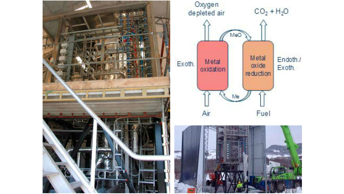
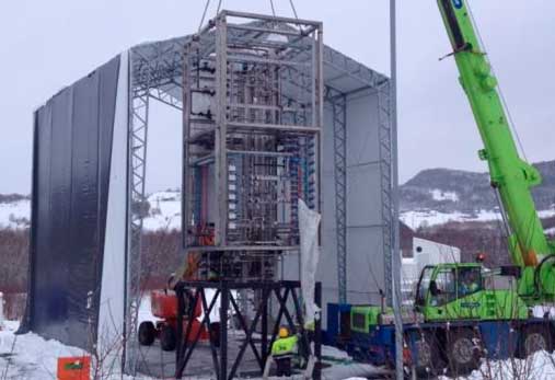
The most recent achievement is the installation of a large test rig of 150 kW capacity installed at Tiller during 2014. The rig is intended for gaseous fuels. The reactors are 6 meters high with diameter of 240 and 160 mm. At this size small scale effects are of minor importance and the results obtained can more easily be transferred to even larger test rigs and demos. Preliminary tests have been done, both at low and high temperatures, but at time being without fuel gas supply. The first tests with fuel gas supply and real reactive CLC operation is planned within 2014. The 150 kW rig is so far the last and largest step in the chain of development and infrastructure built up within the CLC activity of BIGCCS.


Comments
No comments yet. Be the first to comment!