Skip to content

SINTEF Blog Gå til forsiden

  • Energy
  • Ocean
  • Digital
  • Health
  • Industry
  • Climate and environment
  • Building
  • Society
  • EN
  • NO
Energy Ocean

Carbon negative oil – fact or fiction?

CO2 transport requires quantification
author
Grethe Tangen
Senior Research Scientist
Published: 20. Jul 2015 | Last edited: 16. Apr 2025
3 min. reading
Comments (0)

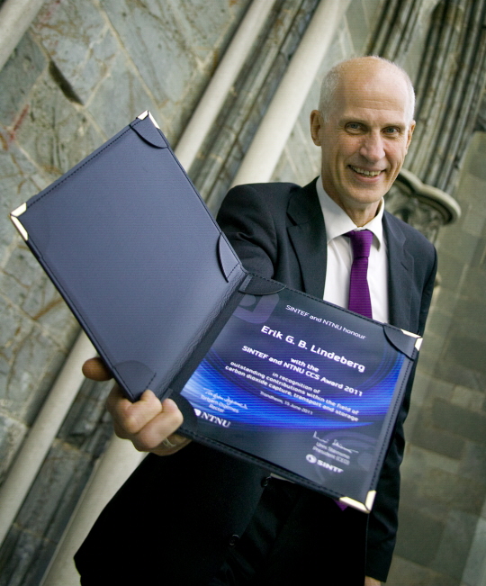
According to Chief Scientist Erik Lindeberg at the TCCS-8 it is possible to produce oil with a negative carbon footprint. Together with colleagues at SINTEF Petroleum Research, Lindeberg has conducted a study commissioned by the Norwegian Petroleum Directorate. The goal was to estimate CO2 storage capacity in suitable oil fields and nearby saline aquifers which can be used as buffer capacity to obtain stable CO2 deliveries.

There are many large oil fields being produced by water flooding at the Norwegian continental shelf. Several are mature and characterised by high and increasing water cut. To govern the remaining resources there is an urgent need to deploy new methods to mobilise the typical 40 -60% of the remaining oil in the reservoirs.

Chief scientist Erik Lindeberg of SINTEF Petroleum Research was awarded the international research prize “The SINTEF and NTNU CCS Award” in 2011 for his pioneering role in research on storing CO2 in geological strata. (Photo: Gry Karin Stimo/SINTEF)

Based on a screening of 40 oil fields, 23 mature water flooded North Sea oil fields were selected as candidates for CO2 injection. Despite the fact that the fields were exhausted due to water flooding, simulated CO2 flooding gave 320 million Sm3 EOR oil, representing 7 % of OOIP (original oil in place) or 20 % relative increase in yield. 1.3 Giga tonnes of CO2 were stored in the oil fields. The Skade/Utsira  formation and the Frigg area were chosen as saline aquifers for excess CO2 and in the simulation 1.7 Giga tonnes of CO2 were stored in buffer aquifers.

The CO2 formed by combustion of the EOR oil amounts to 833 Mega tonnes and is thus, far below the stored CO2.

A techno-economic analysis estimates a total investment of 42 billion USD.  The estimated operating and capital costs of the concept (redesign of platforms, transport, capture, injection of excess CO2) are to large extent covered by the value of EOR oil even at the present low oil prices.

Lindebergs conclusion is that this oil actually can be produced with negative CO2 footprint even if all the EOR oil is combusted and the CO2 from combustion is taken into account. In the injection scenario 70 million tonnes of CO2 was injected annually over 40 years. The largest cost element is a number of new production wells. Obviously, the economy of the total project depends on the oil price, but with oil price of approximately 85 USD/bbl the project may pay 50 USD per tonne CO2 (on the same order as large scale capture cost) and give an interest rate of 7%.

Lindebergs conclusion is that this oil actually can be produced with negative CO2 footprint even if all the EOR oil is combusted and the CO2 from combustion is taken into account.

Reference: Large Scale Tertiary CO2 EOR in Mature Water Flooded  Norwegian Oil Fields. Erik Lindeberg, Alv-Arne Grimstad, Per Bergmo, Torleif Holt, and Dag Wessel-Berg. Presentation at TCCS-8, 17 June 2015.

Comments

No comments yet. Be the first to comment!

Leave a comment Cancel reply

Your email address will not be published. Required fields are marked *

More about Energy

Infographic showing the flow of thermal energy storage (TES) from surplus heat or cold to end users. On the left, red and blue thermometer icons represent surplus heat and cooling, accompanied by the text “Surplus heat or cold – Captured and stored for when it’s needed.” In the centre, a large panel titled “Thermal Energy Storage (TES)” presents three storage technologies. The top section, “Sensible TES,” shows a container with a thermometer and the text “Stores heat in one single phase.” The middle section, “Latent TES,” shows a water droplet and snowflake connected by circular arrows, with the text “Stores heat through phase change.” The bottom section, “Thermochemical TES,” shows two connected coloured circles that separate and reconnect, illustrating a reversible reaction, with the text “Stores heat through reversible reactions.” A large pale arrow-shaped wedge points from the TES panel toward the right side of the figure. On the right, three application areas are shown in separate boxes with icons: industrial processes, buildings, and data centres. The layout conveys that surplus heat or cold can be stored using sensible, latent, or thermochemical TES technologies and later supplied to industrial facilities, buildings, and data centres.

Thermal energy storage is already commercial  

Jorge Salgado Beceiro
Research Manager

Burning ammonia cleanly: How timing changes everything 

Author Image
Author Image
2 forfattere

Capturing CO₂ from waste: 14 lessons on turning a hard idea into a real project

Author Image
Author Image
Author Image
3 forfattere

Technology for a better society

  • About this blog
  • How to write a science blog
  • Sign up for our newsletter
  • News from NTNU and SINTEF
  • Facebook
Gå til SINTEF.no
SINTEF logo
© 2026 SINTEF Foundation
Privacy Editorial Press contacts Website by Headspin