

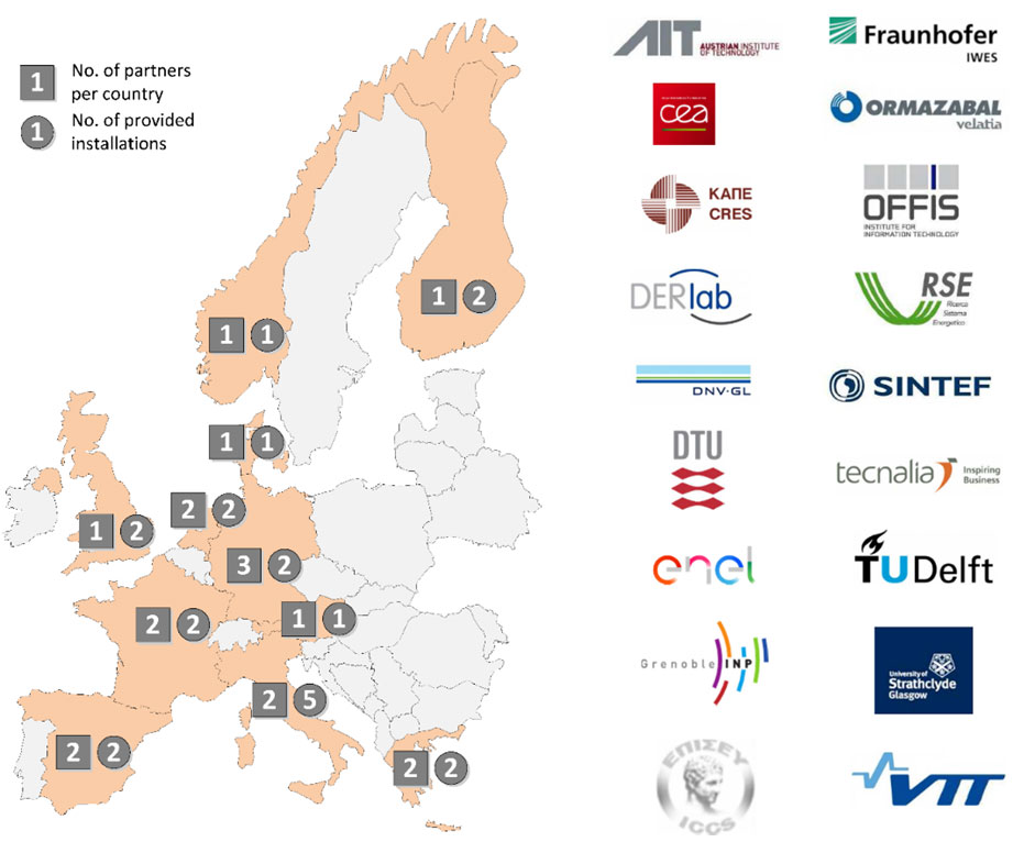
The EU H2020 research project ERIGrid addresses the absence of an integrated approach for analysing and evaluating complex configurations in Smart Grids by optimizing the use and the further development of the best Smart Grid research infrastructures in Europe. The ERIGrid infrastructure operates under an integrated approach of 21 distributed installations located in 11 countries.
Within the ERIGrid project, the Transnational Access (TA) scheme provides access to these state-of-the-art laboratories for researchers and scientists to conduct experiments of their competitively selected proposals.
- The TA includes free travel and lodging for the stays while offering the research infrastructure along with logistical, technological and scientific support.
Further information of the ERIGrid project with the description of the offered Research Infrastructures is available on the ERIGrid website.
Hurry up! The deadline for the third call is 15th of November 2017.
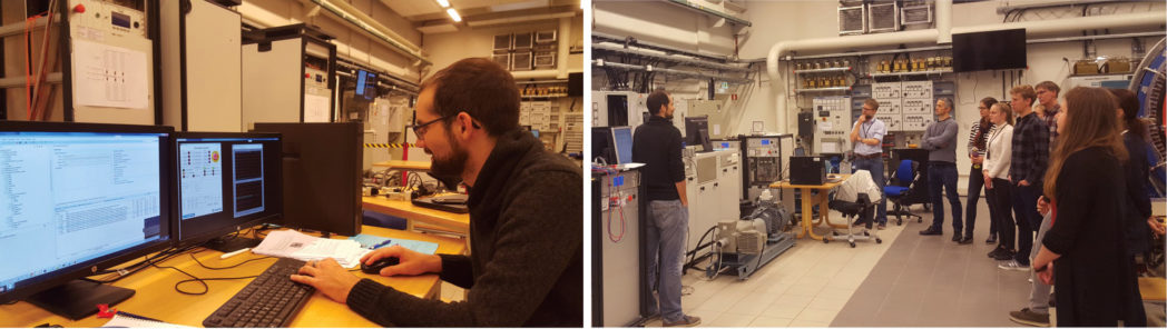
As part of the ERIGrid infrastructure, our Norwegian National Smart Grid Laboratory (NSGL) is offering its facility for the projects selected by the independent user selection panel.
Until now, two experiments have been successfully conducted by international guests and the third one is in preparation.
The first guests
The first project is titled ‘Reliability Enhancement in PV Rich Microgrids with Plug-in-Hybrid Electric Vehicles (PHVEs) and Data Centres (DC)’. In this project a tool developed to optimally integrate DGs with PHEVs and data Centers (DCs) to enhance the reliability of microgrid is tested in laboratory in Power-Hardware-In-the-Loop setup.

The second guest
The second project is called Transient Control in Microgrids (TCMG) aiming to test a new transient control method which is based on the dynamic phasor model of a grid that considers the electro mechanic and electromagnetic dynamics of the system. The purpose of the experiment is to validate the proposed control and modeling approach with a comprehensive experimental setup that contains multiple dispatch able inverter interfaced generation and storage units, as well as synchronous generators.
Testament
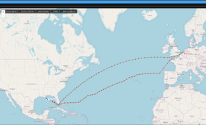
We had a short interview with Christoph Kammer from Ecole Polytechnique Fédérale de Lausanne.
- How do you come to know about the ERIGrid transnational access program?
CK: Through another PhD student who applied to ERIGrid during an earlier call.
- Why did you chose the Norwegian National Smart Grid Laboratory in your application?
CK: The chosen facility was able to provide all necessary tools (a real-time simulator, a state-of-the-art PHIL* setup with multiple inverters and rotating machines, the ability to conduct experiments at realistic power and voltage levels)
- Please describe in short about your project in the lab.
CK: The focus of our research lies on device-level as well as primary and secondary control design in power systems.
The project comprised of two main experiments:
- The first experiment concerned the design of current controllers for multiple parallel inverters using a novel control design method.
- The aim of the second experiment was to validate a new distributed control approach that combines primary and secondary control in a unified framework.
Both experiments required a PHIL setup, combining a real-time simulation of a power grid in OPAL RT ** and two to three real inverters. This setup allows to achieve realistic results that include many nonlinear effects and dynamics that are very hard to model in simulation. Especially for the first experiment we managed to obtain great results that match very well with the expected values generated in simulation.
The data will be valuable to further reinforce the potential and applicability of the proposed control design method, especially when addressing people from the power systems field.
- Did you find what you expected in the laboratory?
CK: The laboratory provided most things I was expecting to find, and offered good solutions when components were missing. Overall, the experiments could be conducted as planned.
- What advices would you give for the better advancement of the NSGL facility?
CK: Most issues were already discussed in person, and are already being worked on. Two main points I would highlight is:
- Achieve a more thorough understanding of how to achieve stability of the PHIL feedback loop in order to prevent unnecessary delays.
- If the number of groups using the lab for experiments increases further, a scheduling system will become necessary to prevent waiting times and overlaps.
* PHIL stands for Power Hardware-In-the-Loop, which is a test system where simulated grid and electrically connected real component are interfaced acting as one system in real-time experiment. ** refers to a real-time digital simulation platform developed by the company OPAL-RT .


Comments
No comments yet. Be the first to comment!