


Security of electricity supply in Norway is generally very good. Electricity consumers experience few power outages, and most outages are brief and limited in scope. This high security of supply did not materialise by itself; it is the result of systematic efforts. As the power system evolves, it’s essential to identify factors that can weaken security of supply and remain vigilant about how to maintain it.
A significant change that is on the horizon is Norway’s ambition to expand offshore wind power generation massively over the coming decades. Integrating offshore wind power into the Norwegian onshore grid will require an offshore grid, and coordinated development of the existing onshore network in parallel with the new offshore network. While the offshore grid will share some similarities with the onshore grid, the two are different on several key points. Much remains uncertain about the specifics of the future grid, but it must be designed and developed in a manner that safeguards security of supply. As some of the design choices are being made already now, we must ensure that we are not introducing new vulnerabilities into the power system.
Identifying potential vulnerabilities
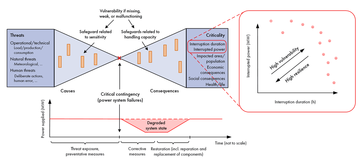
A power system might consistently maintain high security of supply over many years, yet still be vulnerable to exceptional events causing extensive or prolonged outages. A vulnerability can be understood as an inadequate protective barrier against such critical consequences. This concept is illustrated in Figure 1 below, showing a version of the “bow-tie model” often used in risk assessment.
In earlier research projects, SINTEF has developed frameworks and methodologies for vulnerability analysis in power systems, based on this conceptual model. This blog article summarises how this methodology has been used to evaluate potential vulnerabilities in future interconnected offshore and onshore grids. The work was conducted collaboratively between two research projects led by SINTEF Energy Research: 1) “Development of coupled offshore and onshore grids”, a collaborative and knowledge-building project partially funded by the Research Council of Norway, with NTNU, Statnett, Aker Solutions and GE Vernova as partners; and 2) “MISSION”, an EU-funded project developing switchgear technology not reliant on the climate-damaging gas SF₆. The analysis was based on in-depth interviews with eight partners from both projects, including transmission system operators (TSOs) and other stakeholders. The findings were presented at the international CIGRE symposium in Trondheim, in May.
This methodology has been used previously for vulnerability analysis in power systems of various types and sizes. In 2017, we conducted a vulnerability analysis that looked at potential failures of interconnectors between the Nordic power system and neighbouring power systems. The analysis revealed that insufficient system inertia was a critical factor potentially increasing system vulnerability. Before we present our updated and extended analysis, let’s take a moment to explain what system inertia is.
One million coffee machines
A critical aspect of the power system is balancing consumption and production: the amount produced and consumed electricity must be equal from one second to the next. The Nordic power system (Norway, Sweden, Finland and parts of Denmark) is an interconnected alternating current (AC) system with a frequency of 50 Hz. If more electricity is consumed than produced at a given moment, energy is drawn from the rotating masses in power plants, which in turn causes a drop in frequency. Traditionally, system inertia comes from rotating mass in hydro and thermal power plants. With less inertia in the system, the frequency will drop more rapidly.
Consumption changes continuously – for example, it increases slightly when many people turn on their coffee machines in the morning, and then decreases when the machines switch off after brewing. If a coffee maker unexpectedly shuts off early, the imbalance that creates is too minor to affect system operation significantly. Problems arise when a large consumer or important component unexpectedly disconnects, creating an imbalance that is so large that it needs to be carefully managed to maintain system stability. System inertia is the first protective barrier for maintaining this stability.
The power system has multiple barriers to maintain frequency at around 50 Hz, as illustrated in Figure 1. However, excessive imbalances between generated and consumed power can lead to large-scale disconnections or frequency collapse, disconnecting all consumers and producers. The Nordic system is designed to handle a fault of 1.4 GW – which means that up until that amount, it can avoid collapse without needing to disconnect consumers or production. This is therefore referred to as the system’s dimensioning fault. It corresponds to the largest production unit in the Nordics. As a comparison, average power production in the Nordic system is at around 50 GW. The simultaneous disconnection of a million coffee machines would represent a dimensioning fault – such a scenario is of course extremely unlikely. More likely to happen is the failure of a single power cable.
HVDC offshore networks connected to HVAC onshore networks
The Norwegian power system connects with the rest of the Nordic region via high-voltage AC (HVAC) lines, while the Nordic system connects to the rest of Europe through HVDC interconnectors. These inter-country connections are based on direct current technology (HVDC) and consist of HVDC cables with AC/DC converters at each end. An advantage of these AC/DV converters is that they provide greater control over power flow through the DC cables – more so than is viable for AC lines.
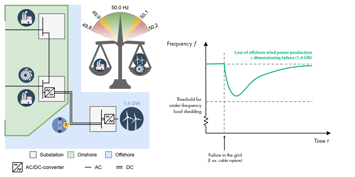
The dimensioning fault principle we have outlined above applies to HVDC cables as well, which limits their capacity to 1.4 GW. This principle will likely also apply to offshore wind farms connected to the Norwegian grid.
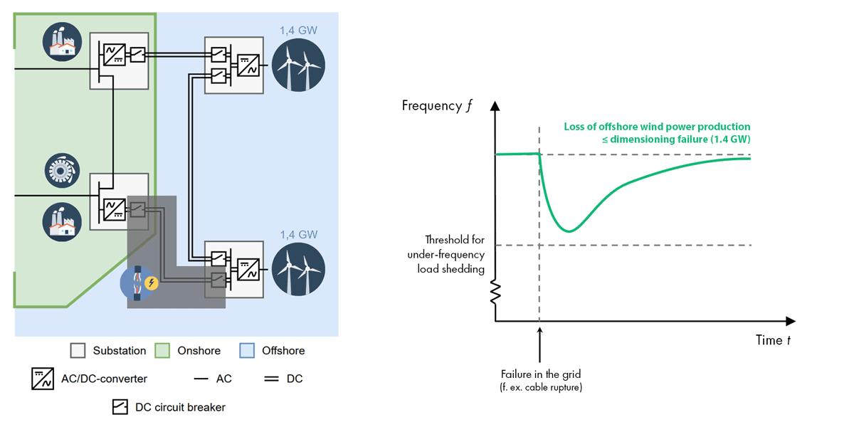
The left part of Figure 2 shows a schematic diagram of an offshore wind farm connected to an onshore HVAC grid via an HVDC cable. Suppose this onshore grid represents the Nordic power system. The offshore wind farm has an installed capacity of 1.4 GW, but due to wind variability, it often produces less than that. A fault in the offshore network (the HVDC cable) could cause the sudden disconnection of up to 1.4 GW of injected power, which would affect the onshore grid frequency as shown in the left part of Figure 2. The greater the power loss and the lower the system inertia, the faster the frequency drops.
The left part of Figure 3 illustrates a possible interconnected offshore and onshore grid, where two offshore wind farms are linked by an HVDC cable that can both relieve the onshore grid and direct offshore wind power to land. A grid that gives electricity multiple paths it can travel through is called a meshed grid. In meshed onshore HVAC grids, protection systems detect faults and open circuit breakers, which isolates faults and maintains transmission in the unaffected parts of the grid. However, a fault anywhere in the HVDC grid depicted in Figure 3 necessitate the disconnection of the entire offshore grid, and of all wind power production. This poses a significant risk: the frequency can drop to such a level that consumers need to be disconnected to prevent a frequency collapse. This illustrates that such offshore and onshore grids, when coupled together, are vulnerable to faults occurring offshore.
In Figure 3, the offshore grid is connected only to the Nordic power system. If it was connected to both the Nordic system and to the continental-European, the loss of offshore wind production would be split between the two systems – making it smaller than a dimensioning fault. The risk of frequency drops in such a situation would be lower than in a scenario where offshore wind is connected only to the Nordic system.
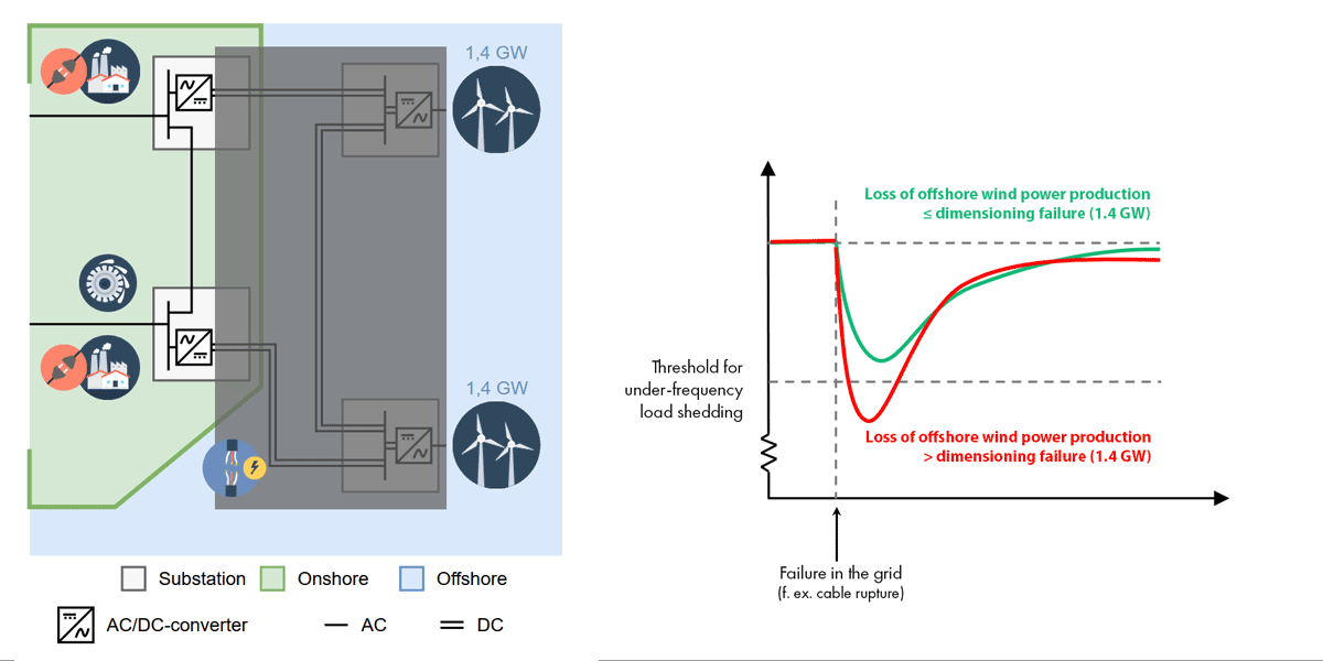
Figure 4 also shows what happens in a similar situation if the offshore grid has HVDC circuit breakers installed to isolate faults to limited sections of the grid. In this case, the offshore grid might not have the required capacity to transmit production from both offshore wind farms to land, but the loss of power is still significantly less than in Figure 3.
The MISSION project is developing new HVDC switchgear technology, but HVDC circuit breakers capable of interrupting the flow of electricity in case of a fault remain some distance away. One challenge is that it is more difficult to interrupt DC current than AC current. AC current in a conductor is alternating up and down at a frequency of 50 Hz, passing through zero current 100 times per second (once on the way up, and again on the way down). When the current passes through zero, it can be interrupted by separating two sides of the conductor using either an electrically insulating gas or a vaccum. DC current does not oscillate in the same way and must be “forced” to zero before it can be interrupted. DC fault current is absorbed by the DC breaker when it is “forced” to zero, which significantly increases its size compared to an AC breaker. This makes it very costly to place HVDC circuit breakers on the platforms where HVDC/HVAC converters are located, near offshore wind farms.
Potential vulnerabilities related to interconnected offshore and onshore grids
System inertia and dimensioning faults were among several aspects examined in the vulnerability analysis. Results from the entire analysis are summarised in Figure 5. In addition to vulnerabilities associated with the availability of HVDC circuit breakers, critical fault events and relevant threats are mapped to the bow-tie model.
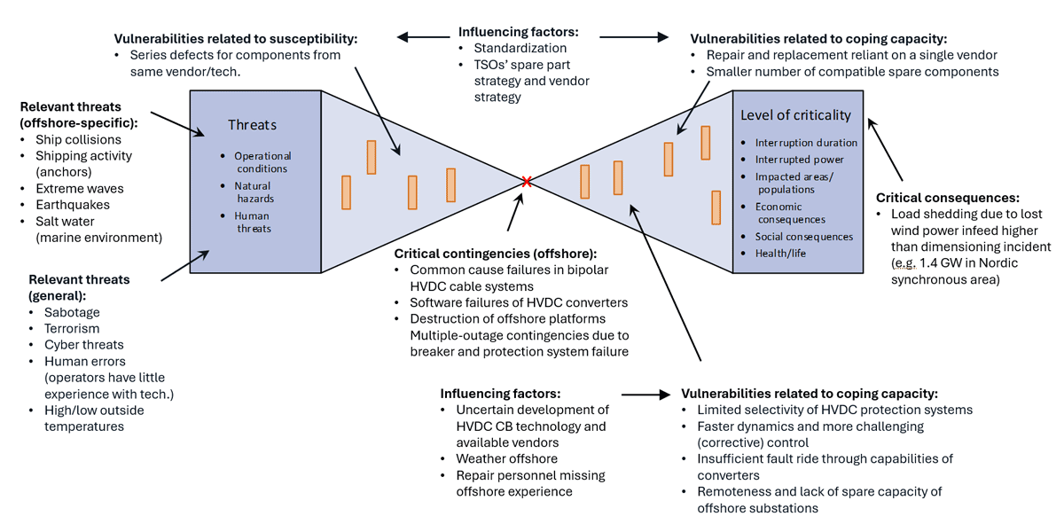
The figure also illustrates some of the factors influencing vulnerability. For example, there is a dilemma whereby standardisation of technology for components such as breakers and converters can impact vulnerability both positively and negatively. On the one hand, such standardisation makes system operators less dependent on individual suppliers for such things as component repairs and replacements. On the other hand, it increases the likelihood of introducing the same vulnerability into component designs.
Measures to reduce vulnerability and strengthen resilience
The conclusions from the study can be summarised as the following recommended barriers that should be put in place to reduce vulnerability and strengthen resilience to safeguard the security of supply of coupled offshore and onshore grids:
- Development of HVDC circuit breaker technology should be supported and strengthened. This should be done in a way that ensures multiple suppliers of technology and components are available in the future.
- In the absence of offshore circuit breakers, the scope of meshed HVDC grids should be limited. For potential grid solutions for interconnected offshore and onshore grids, one can quantify fault risk by examining both the probability of different-sized outages and their consequences in terms of loss of load and the need for reserve capacity.
- Alternatively, simpler breaker technology and risk-based operation can be employed. By monitoring the amount of production and available system inertia at any given time, offshore grids can be operated in such a manner as to maintain fault risk within acceptable limits.
- HVDC grids do not only create problems; they can also be part of the solution. The controllability of HVDC/HVAC converters can be leveraged to make the power system more robust, for example by providing “synthetic” system inertia.
Although this article focused on the Norwegian and Nordic power systems, similar issues exist throughout Europe and in other parts of the world. When developing power systems, international collaboration is essential, as is learning from experience and mistakes made elsewhere.
Concluding remarks
We do not know what the grid will look like in the future, but the building blocks of a future interconnected offshore and onshore grid are being developed right now. By “building blocks”, we refer to both physical components and technologies, as well as methods and models for analysing and assessing possible solutions and development pathways for the power system. To achieve this effectively, we must view power systems and their components holistically, and collaborate across the value chain – from component and technology suppliers to power system planners and operators.
This article is based on SINTEF’s results and analyses from the research projects, and does not necessarily represent the views, principles and strategies of the project partners.


Comments
No comments yet. Be the first to comment!