
Recently, we were granted funds from The Research Council of Norway through the EnergiX programme to continue this effort through the FerroCool project.
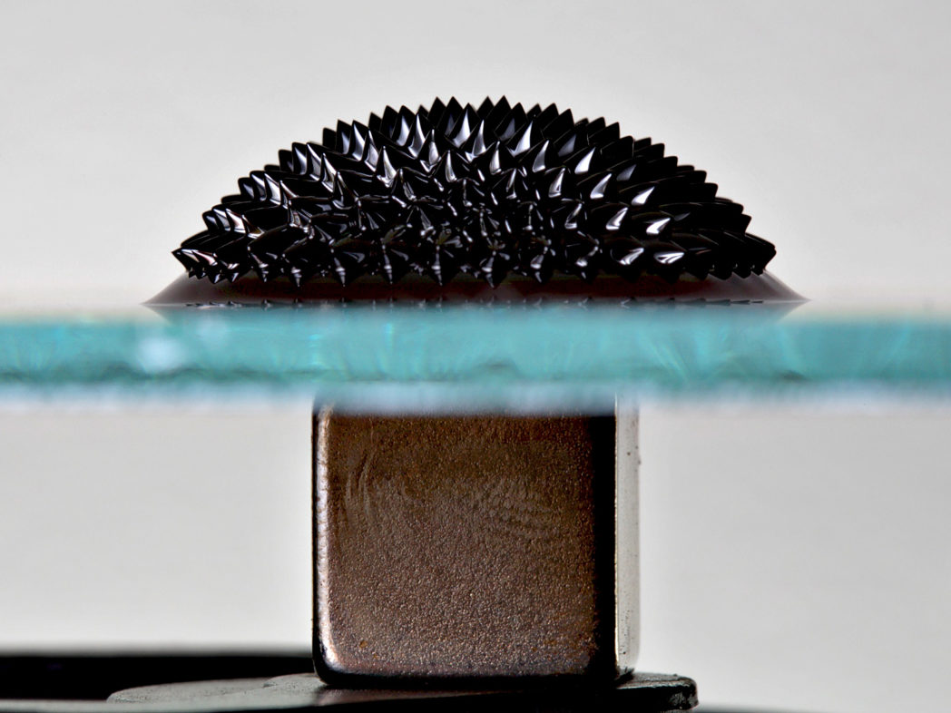
Ferrofluids are liquids with extremely small, magnetic nanoparticles added. The particles are often as small as 10 nanometers in diameter. This corresponds to the length of 30 water molecules placed end to end.
(..)the length of 30 water molecules placed end to end
Adding nanoparticles to a cooling fluid gives several advantages that are important for cooling systems. One is improved fluid-to-wall heat transfer. This is important to have as much as possible of the dissipated heat transferred to the fluid and transported away. Another is thermomagnetic pumping, an exotic physical effect by which the fluid can be pumped using magnets when it is heated. These advantages enable compact cooling systems without moving parts (such as conventional pumps) that require less maintenance than current systems.
FerroCool: Cooling electric cars, solar cells and wind turbines
One application of this technology is cooling of semiconductor components in power converters. Cooling these is important since they produce a significant amount of heat in a small area and because they will break down if they become too hot.
Power converters find lots of applications, for instance where it is necessary to change the frequency of alternating current or converting between alternating current (AC) and direct current (DC). Examples are:
- Electric cars (DC for the battery must be converted to AC power to the motor)
- Solar cells (DC from the cells must be converted to AC with the grid frequency)
- Wind turbines (power with a varying frequency given by the rotation of the turbine blades must be converted to the frequency of the power grid)
Even more useful in the future
Due to their importance in production and use of renewable energy, e.g. through introduction of the smart grid technology, power converters will be used even more widely in the future than they are today.
During the past two years, we have developed mathematical models and a preliminary simulation tool that can be used to simulate cooling systems based on ferrofluids or conventional cooling fluids. The models and the simulation code have been described in one of our recently published papers. In this work, it was revealed that the simulation results were particularly sensitive to the predictions of the ferrofluid-to-wall heat transfer. Thus good heat transfer models are critical, but it is currently unclear which models (if any) that are good. Therefore we will study this heat transfer experimentally in the FerroCool project to obtain a better understanding of it and to arrive at better heat transfer models.
(…) we will study this heat transfer experimentally in the FerroCool project to obtain a better understanding of it and to arrive at better heat transfer models.
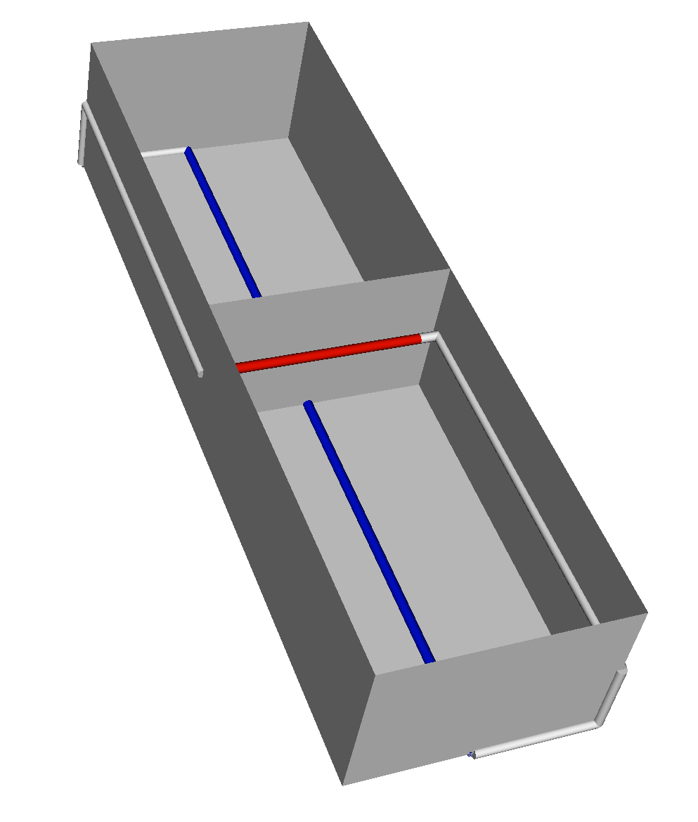
Preliminary simulations are promising and suggest that it should be possible to construct a passive cooling system based on ferrolfuids and magnetic pumping with the capacity (about 15 kW of heat) to cool a power converter serving a 500 kW wind turbine (see figure). This kind of turbine will supply electricity to almost 300 homes when running at full capacity. For comparison, a cooling system of the same size without magnetic pumping or a ferrofluid will only be capable of serving a wind turbine of 170 kW, according to our simulations.
Through further work with our model, new experimental data from the FerroCool project and systematic optimization, we believe it is possible to create low-maintenance cooling systems that are more compact and efficient than those currently available. This will make power converter devices less costly to produce and operate and mean easier and cheaper introduction of smart grid technology and renewable energy.
Want to know more?
See also:
- Ferrofluid and nanofluid heat transfer
- The FerroCool project
- The NanoHX project
- Publication on enhancement of a natural convection loop with a thermomagnetically pumped ferrofluid
Read more on SINTEF Expertice on Ferrofluid and nanofluid heat transfer


Comments
What happens if we detonate hydrogen + O2 in a ferrofluid?
Does it still retain its properties? What changes?