Skip to content

SINTEF Blog Gå til forsiden

  • Energy
  • Ocean
  • Digital
  • Health
  • Industry
  • Climate and environment
  • Building
  • Society
  • EN
  • NO
Energy

GAFT: Progress update on Fischer-Tropsch testing

In GAFT, a Fischer-Tropsch catalyst will be utilized in a medium to high temperature range for synthesis of biocrudes from the gasifier syngas.

author
Roger Khalil
Research Scientist
Published: 25. Jun 2017 | Last edited: 15. Apr 2025
2 min. reading
Comments (0)
  • GAFT website

Catalysts

The productivity of cobalt-based catalysts is known to be much higher than that of iron-based catalysts. However, since iron-based catalysts are much cheaper, impacting on the overall cost of the process, it is debatable whether a cobalt-based catalyst is truly the optimal catalyst for all BTL-processes. Syngas coming from the entrained flow gasifier will typically have H2:CO ratio close to 0.5. To utilize the potential of the Co-based catalyst, increasing the H2:CO ratio in the syngas with water-gas-shift (CO + H2O = CO2 + H2) is necessary.

Laboratory testing

In the GAFT project, six cobalt- and six iron-based Fischer-Tropsch catalysts have been tested in laboratory fixed-bed reactors at relevant FT conditions. All catalysts are tested at reactor temperatures from 210 to 270 °C and H2:CO ratios from 1 to 2, with and without CO2 in the syngas. Selected results obtained with H2:CO = 1.0 are shown below. A general trend is that Fe based catalysts give lower CH4 and higher CO2 selectivity than the Co-based catalysts.

Biofuel production process

For the biofuel production process, many factors might affect efficiency and performance of a catalyst and the final product yield. The project will continue with more detailed process studies on an iron-based catalyst, i.e. the effect of H2/CO << 1 on product selectivity and catalyst stability.
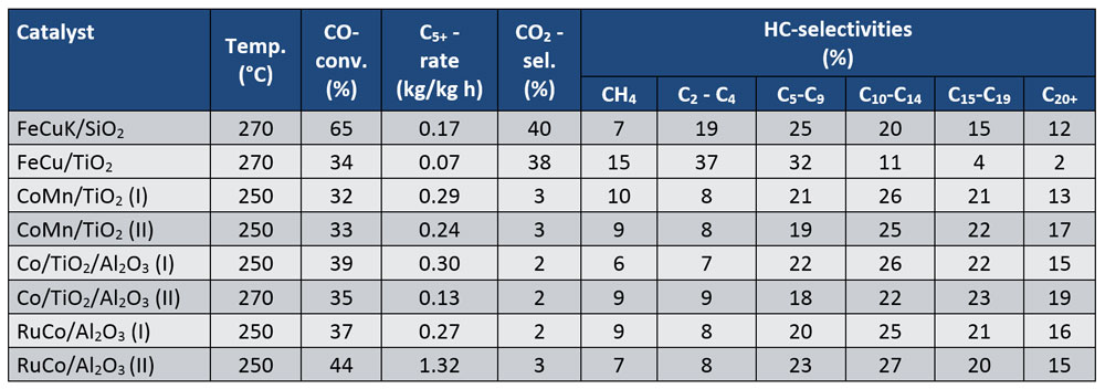
Some results obtained with H2:CO in the syngas feed
Some results obtained with H2: CO in the syngas feed

Comments

No comments yet. Be the first to comment!

Leave a comment Cancel reply

Your email address will not be published. Required fields are marked *

More about Energy

7 trends shaping the green hydrogen economy

Author Image
Author Image
2 forfattere

How much can energy-efficient voyage planning save? Evidence from 11 months of North Atlantic data

Author Image
Author Image
2 forfattere
Infographic showing the flow of thermal energy storage (TES) from surplus heat or cold to end users. On the left, red and blue thermometer icons represent surplus heat and cooling, accompanied by the text “Surplus heat or cold – Captured and stored for when it’s needed.” In the centre, a large panel titled “Thermal Energy Storage (TES)” presents three storage technologies. The top section, “Sensible TES,” shows a container with a thermometer and the text “Stores heat in one single phase.” The middle section, “Latent TES,” shows a water droplet and snowflake connected by circular arrows, with the text “Stores heat through phase change.” The bottom section, “Thermochemical TES,” shows two connected coloured circles that separate and reconnect, illustrating a reversible reaction, with the text “Stores heat through reversible reactions.” A large pale arrow-shaped wedge points from the TES panel toward the right side of the figure. On the right, three application areas are shown in separate boxes with icons: industrial processes, buildings, and data centres. The layout conveys that surplus heat or cold can be stored using sensible, latent, or thermochemical TES technologies and later supplied to industrial facilities, buildings, and data centres.

Thermal energy storage is already commercial  

Jorge Salgado Beceiro
Research Manager

Technology for a better society

  • About this blog
  • How to write a science blog
  • Sign up for our newsletter
  • News from NTNU and SINTEF
  • Facebook
Gå til SINTEF.no
SINTEF logo
© 2026 SINTEF Foundation
Privacy Editorial Press contacts Website by Headspin