Floating offshore wind (FOW) is pivotal in Europe’s energy ambitions. Nevertheless, there is a pressing need to decrease costs. A significant material and installation cost is associated with the mooring system, and developers are therefore looking into new mooring concepts for FOW farms.
One proposal is to introduce shared mooring lines suspended between two floaters in a farm, in addition to traditional anchor lines, suspended between a floater and the seabed.
Simulating wind farms with shared mooring – and the need for faster methods
The shared mooring lines represent mechanical couplings which needs to be included in simulations and analysis. Shared mooring systems are currently a topic of research in both SFI BLUES and CYBERLAB KPN, funded by the Research Council of Norway and industrial partners.
High fidelity simulation software capable of dealing with systems of interlinked floaters already exists, like Orcaflex and SIMA, the latter developed by SINTEF Ocean. These tools are typically based on the nonlinear finite element method (FEM) and have the drawback of being computationally demanding and requiring many hours or even days of number crunching to deliver the answers we need in terms of max offset, extreme line tensions and fatigue lifetime. This is a bad fit with the design engineer’s need to analyse a vast number of design alternatives and load cases in the quest to find the best design. Both simplified (and fast) methods, as well as high fidelity (and slower) methods, are needed in design work. This is true for a single floater, but even more so for a coupled system of FOW turbines.
Developing simplified methods without sacrificing too much accuracy is all about including the physical effects that matter for the problem at hand, while leaving out the physical effects that don’t matter. One widely used simplified mooring line model, available in SIMA (in the SIMO engine), MIMOSA and Orcaflex, is the quasi-static model which neglects dynamic effects caused by damping and inertia. This model works satisfactorily in some cases, although it typically needs to be “fixed” by adding the missing damping empirically based on model tests or higher fidelity models. In other cases, in the presence of stronger dynamic line effects, quasi-static results are just plain wrong. For these cases, we need to reconsider the assumptions and include the missing physical effects.
Yet, another simplification is obtained by linearization. A linearized model, either quasi-static or full dynamic, can be analysed in the frequency domain, which is particularly fast. However, moored floaters in extreme sea states typically exhibit large amplitude low-frequency motions (slow-drift) beyond the range where the mooring lines have linear behaviour. Furthermore, frequency domain tools must analyse wave-frequency (WF) and low-frequency (LF) responses separately, despite the strong nonlinear interactions that we know exist between WF and LF response components. While frequency domain methods surely have their use cases, more accurate yet still fast methods are needed.
A new method for fast simulation of line dynamics
Motivated by the need for faster methods, and the shortcomings/inaccuracies of existing simplified methods, a new simplified mooring line model has been developed as part of the SFI Blues project. Before diving into the inner workings of the new method, let’s try to answer the most important question: Does it work?
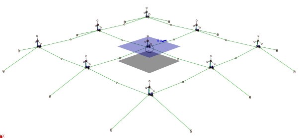
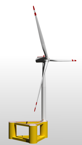
We have recently tested the method on the WINDMOOR floater – a semi-type floating wind turbine developed as part of the WINDMOOR KPN project, and available as an example model in the SIMA software package. The WINDMOOR floater has three identical mooring lines, each with a 25-metre-long top chain, 170 metre fibre rope and a 400-metre bottom chain, located at a water depth of 150 metres. First, we have run SIMA with a coupled SIMO-RIFLEX model for an extreme sea state to obtain the floater motions and anchor line tensions. Then, the floater motions from SIMO-RIFLEX were used to prescribe the motions of the fairleads for the new method. The same was done on a traditional quasi-static model for comparison. The figure below shows a comparison of the tension time series in the three lines with the three methods.
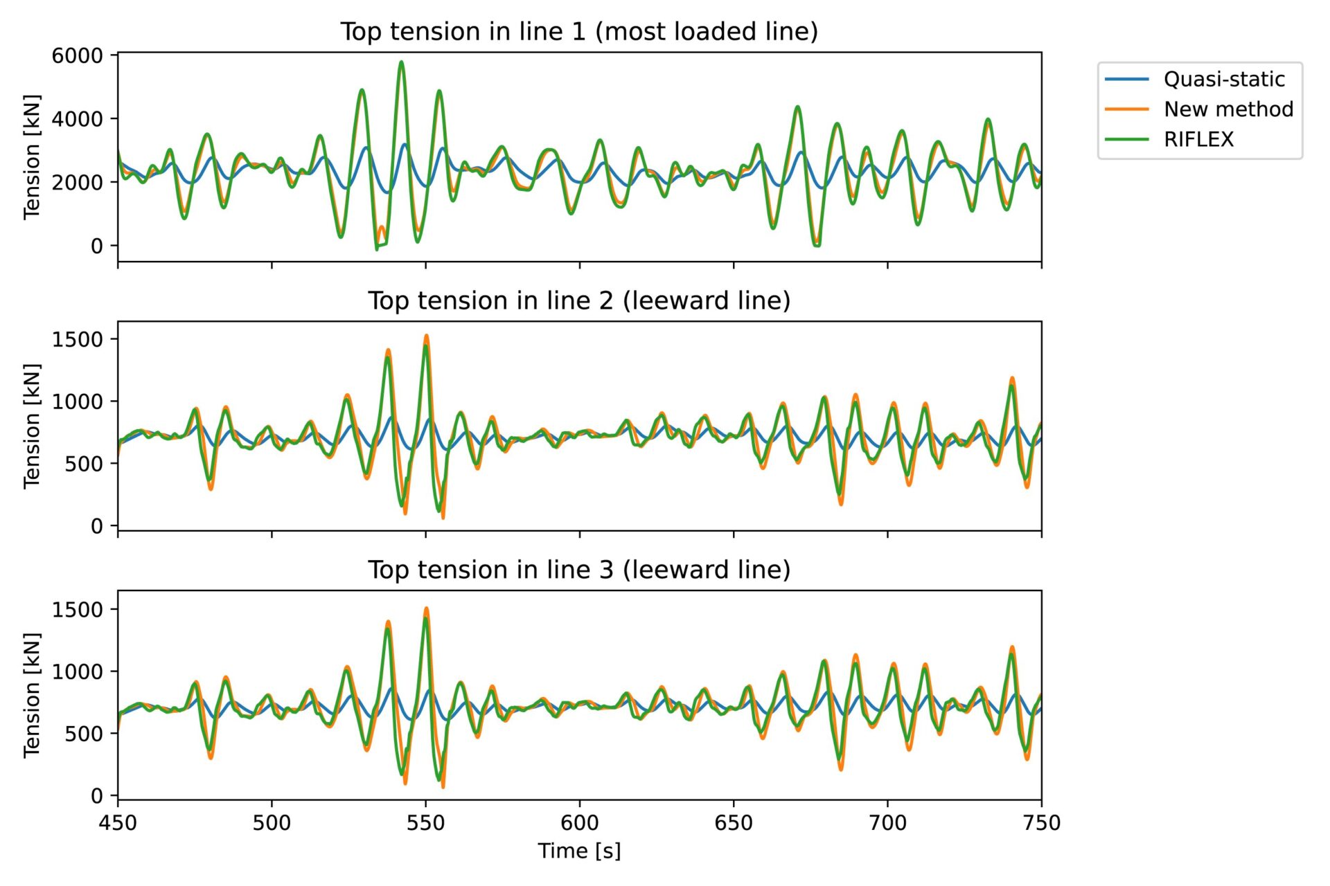
This is a case where the quasi-static model fails completely, while the new method gives a very good approximation to nonlinear FEM (SIMO-RIFLEX). In addition to the large general underprediction of tension by the quasi-static model, a clear phase difference can be observed. The peaks in the tension predicted by the new method and by FEM occur earlier than the quasi-static peaks. This is because of drag loads, which give forces in phase with the floater velocity – damping forces. These damping forces are very important for the low-frequency motion of the floaters, and the fact that it is captured by the new method is an indication that it will be well suited for motion predictions. This also implies that the tension estimate can be verified, or improved, by running nonlinear FEM analysis with prescribed fairlead motion for selected lines – so called un-coupled mooring analysis.
Although the motivation for the new method is wind turbine farms with shared mooring, the first version of the software implementation is restricted to anchor lines. We need to generalize it to support shared lines as well. We also need to apply the method to new systems and conditions to draw up the domain of validity. Will it work equally well in deeper water? What about systems with clump weights and buoys? A scientific publication is also on the plan. When thoroughly validated it is important to make the new model available to the industry through our software package SIMA. Today, the new method is part of a newly developed software library called fmoor.
How it all works (technical content alert!)
We promised some more details on the inner workings of the method as well, so here we go. The new method is inspired by the so-called simplified analytic method (SAM), available in the frequency domain mooring analysis tool MIMOSA. The major drawback of SAM is that it is linear while our proposed new method is fully nonlinear. The derivation of the new method is based on the energy methods from analytical mechanics developed during the 18th century and later. Whereas Newtonian mechanics, developed a century earlier by Isaac Newton, is restricted to vector quantities of motion, analytical mechanics generalized Newton’s equations of motion to allow for arbitrary choices of coordinates known as generalized coordinates. Analytical mechanics is the foundation of modal analyses in structural mechanics, where the deformation of a structure is described as a weighted sum of predefined mode shapes. Modal analyses are usually carried out for linear structural models, and the mode shapes are usually taken as the eigenmodes of the structure. The assumption of linearity and selection of eigenmodes as mode shapes gives particularly simple and de-coupled equations of motion. But neither linearity nor the selection on eigenmodes as mode shapes are requirements in analytical mechanics, and our new mooring line model is indeed fully nonlinear.
Formulating non-linear equations of motions based on analytical mechanics starts with writing out two scalar energy functions, 1) the total potential energy as a function of the generalized coordinates, and 2) the total kinetic energy as a function of the generalized coordinates and its time derivatives. The forces associated with potential energy stems from gravity, buoyancy, and elastic strains. These represent stiffness or restoring forces. The forces associated with kinetic energy are inertia forces due to the mass and added mass of the line. The stiffness and inertia forces must be balanced by external loads due to forcing of the line-ends (from the seabed and floater) as well as loads along the line due to hydrodynamic drag, including both damping and excitation effects. The magnitude of the generalized external loads is a product of both load distribution along the line and how well the load pattern matches the given mode shape.
At this point we make an important assumption: That the inertia effects can be neglected, simply by setting kinetic energy to zero. This assumption can be backed up by looking at the Keulegan–Carpenter (KC) number characterizing the flow across the mooring line cross-section. The KC number is the ratio of motion amplitude to mooring line diameter. A high KC number means that viscous flow effects become more important relative to inertia effects which is indeed the case for mooring lines.
What about selection of mode shapes? These must reflect the physical effects included in the model. When only potential energy effects (gravity, buoyancy, and material strain/stress) are included we know that the mooring line will assume a static catenary shape, following the elastic catenary equations. So, the catenary shape seems like a good starting point. But we have an additional physical effect included: viscous drag along the line. For this reason, we must include a small perturbation to the catenary shape. This perturbation allows the line to elongate in response to the drag loads. This additional deformation in the mode shape must also be accompanied by an additional term in the potential energy function to get the forces right. While the elongation is very small in terms of displacements, it becomes larger when differentiating with time to obtain velocity. In fact, this small additional elongation has an important role in “moderating” the drag loads by filtering out the high-frequency content from the normal velocity along the line. Prescribing an unmodified catenary shape and including drag loads will simply not work – the normal velocity and resulting drag loads along the line will be grossly overpredicted. The extra elongation fixes this and allows our model to capture a physical phenomenon known in the literature as “drag locking”. Drag locking is what happens when high-frequency fairlead-end oscillations activate very large normal drag loads along the line, to an extent where the line is almost laterally restrained, allowing only elastic and axial deformations.
Energy methods vs traditional finite element methods
The attractiveness of the energy methods lies in the arbitrariness of the motion coordinates and associated mode shapes. When they are selected wisely and with knowledge of the problem at hand, we can get away with only a few coordinates. Our model uses only three coordinates to describe the response of the anchor line. This is one or two orders of magnitudes smaller than the number of coordinates needed in a finite element method, where all nodes along the lines have 3 coordinates each. In other words, we have much fewer equations to solve. Our equations are also “nicer” than those coming from finite element methods – nicer in the sense that they do not include stiff/fast dynamics. The fast dynamics often have little physical significance but still need to be resolved by using an overly small time step, and quite often cause havoc (crashes the simulation!)
One potential drawback of the energy methods is the headache associated with writing out mathematically the energy functions – and even worse – to compute the derivatives of the energy function with respect to all the generalized coordinates. Writing out the potential energy is manageable in our case. When it comes to computing the derivatives, we make use of a fascinating computational technique known as forward-mode automatic-differentiation via operator overloading, in the following just called autodiff. Autodiff is a method which provides exact derivatives without having to write out the answer analytically as source code.
We strongly believe that the energy methods from analytical mechanics together with automatic differentiation of the energy functions is a very good fit and gives us what we need to develop methods which are both fast and accurate. Variations of the mooring line model which includes inertia effects and add new mode shapes that allow for richer response patterns, when this is needed, is also a possible path for future development.
0 comments on “Faster simulations of floating wind turbines with shared mooring”