

The geological storage of CO2 is an essential component for enabling the efficient generation of emission-free hydrogen (H2) as a transport fuel. The large volumes of CO2 produced in the natural gas reforming H2 manufacture require a coupling with direct CO2 separation techniques, and safe geological storage.
Guest authors:
- Alba Zappone (Swiss Seismological Service & Department of Mechanical Engineerin, ETH Zurich, Switzerland)
- Michèle Marti (Swiss Seismological Service, ETH Zurich, Switzerland)
- Melchior Grab (Department of Earth Sciences, ETH Zurich)
- Quinn Wenning (Department of Earth Sciences, ETH Zurich)
- The SCCER-SoE team
For the latter it is important to guarantee both quality and security of storage, for example ensuring adequate injection rate, long term containment, and robust monitoring tools. The experimental approach plays an essential role, both at laboratory and at pilot test scale. The first scale provides input parameters for numerical simulations on the behavior of CO2 and hosting rocks at depth; the second validates modeling, and proves the technology at a scale that is small enough to be safe for experimental testing, but large enough to be significant.
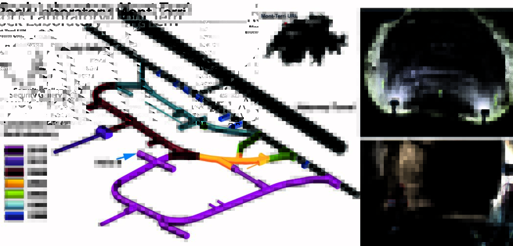
A key challenge for geological storage is played by the integrity of the caprock. Within ELEGANCY, this challenge is addressed by executing a decameter-scale experiment at the Mont Terri Underground Rock Laboratory (URL) in Switzerland. The pilot scale experiment will provide intact samples for laboratory tests both on the fault and on the host rock.
The Mont Terri experiment enters its operational phase
After an intense planning phase, the experiment at the Mont Terri Underground Laboratory has entered its operational stage.
The niche 8, where the experiment is hosted, was drilled and completed with a thick cement floor in May, and equipped with electrical and WiFi connections (Figure 1).
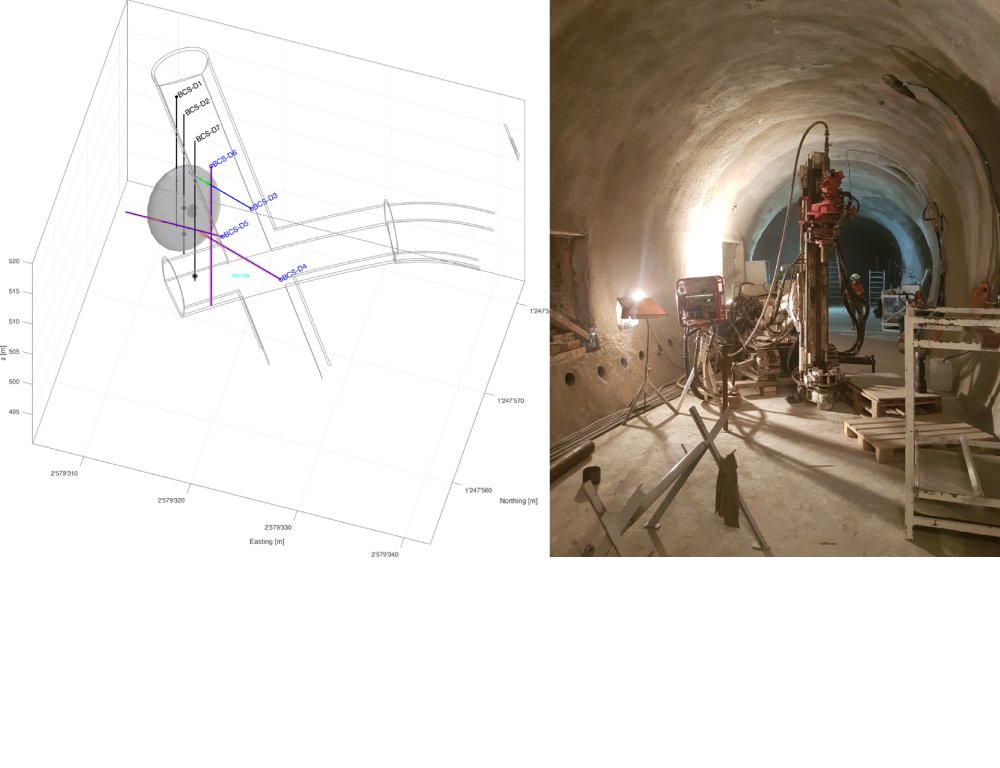
Drilling operation started on August 28th (Figure 2). To date, two of seven boreholes are completed: BCS-D6 (vertical) has a total depth of 36.65 m; BCS-D3 (inclined 45°) is 31.5 m long.
Rock cores (Figure 3) from the first vertical borehole helped to update the fault geometry and to plan the other boreholes. The fault has been reached at a depth only slightly greater than expected, and has a variable thickness of approx. 3 m.
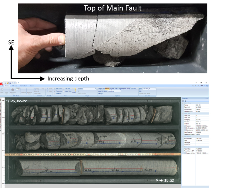
Cores are described for geology/structures and visually scanned; data are entered in a database. Immediately after being described and scanned, selected cores are conditioned (vacuum conservation) in order to prevent changes in fluid content and mineralogy, and thereby in their mechanical properties. Selected cores are sent, upon request, to labs in Switzerland and abroad, for petrophysical and mechanical characterization.
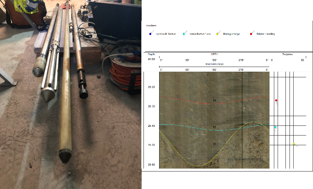
Short after drilling, the boreholes are logged with an optical televiewer, spectral gamma, induction (resistivity), and 4- or 1-arm caliper logs (Figure 4) in order to gain information about the internal geometry of the borehole, and about the structures of the rocks at the borehole walls; all these parameters will help to reconstruct the in situ stress conditions.
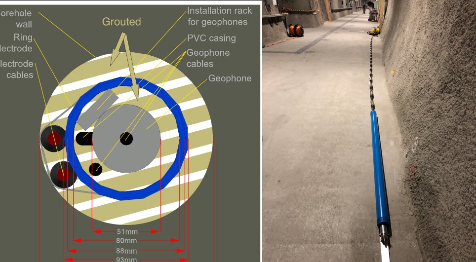
Due to the swelling properties of the clay rock, the boreholes need to be cased as soon as possible after drilling, to prevent them from collapsing. Electrode cables are placed to measure electrical resistivity and fibre optics to measure strain in the cement between casing and borehole wells. Geophones (Figure 5) and other seismic sensors are installed inside the casing, in order to monitor variations of seismic velocities around the injection, and to register possible micro-earthquakes.
The drilling, coring and logging phases will continue until November, after that we will start our injection and monitoring activities.
References:
Guglielmi Y., Birkholzer J., Rutqvist J., Jeanne P., Nussbaumb C., 2017. Can Fault Leakage Occur Before or Without Reactivation? Results from an In Situ Fault Reactivation Experiment at Mont Terri. Energy Procedia, 114, 3167-3174.
Contact person: Svend Tollak Munkejord


Comments
No comments yet. Be the first to comment!