

The cable construction itself is very durable and have few faults. A major part of insulation resistance degradation or faults involving cables are therefore located in:
- cable connection points, like wet mate connectors
- connections to subsea control modules (SCM)
- subsea distribution units (DSU)
- manifolds
- Xmas Trees
- pumps, compressors or transformers
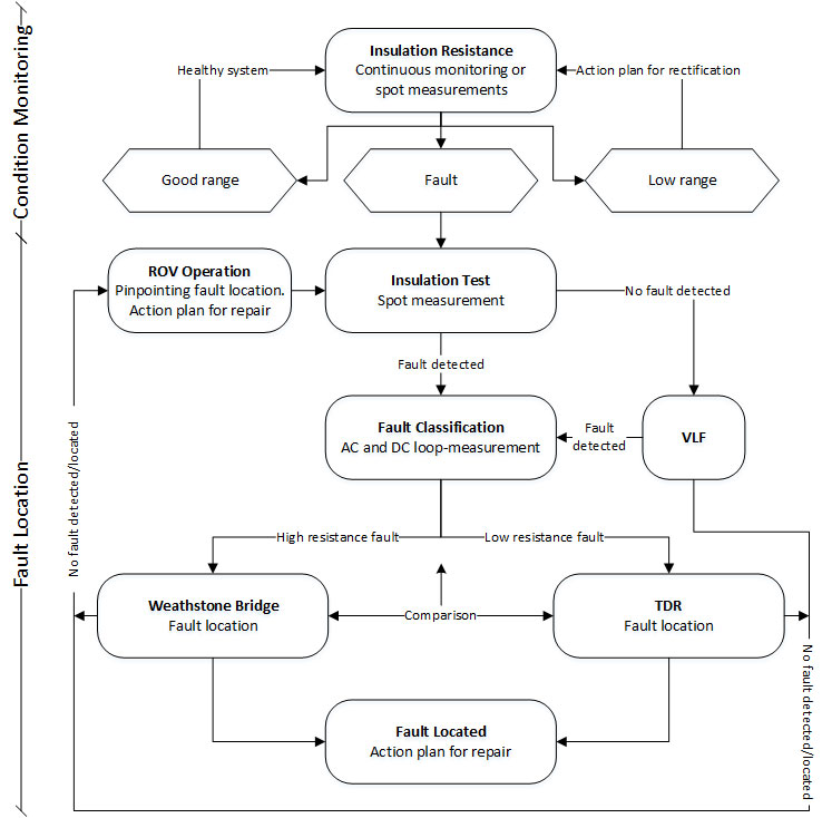
Since subsea equipment is inaccessible without ROV operations, fault detection campaigns or condition monitoring are carried out from production platform or vessel. This could be tens or hundreds of kilometres away from a fault. A generic flow diagram for fault detection and location is shown below.
Degrading Electrical System
Trending of the insulation resistance over time provides the best condition monitoring and foundation to uncover degrading electrical subsea components. By comparing with previous recordings, it may be possible to stipulate actions to be taken in preventive maintenance programs.
This way, sudden, time consuming and expensive failures may be limited or avoided.
If trending is not available, spot readings will indicate if the insulation is good or bad.
Fault Verification
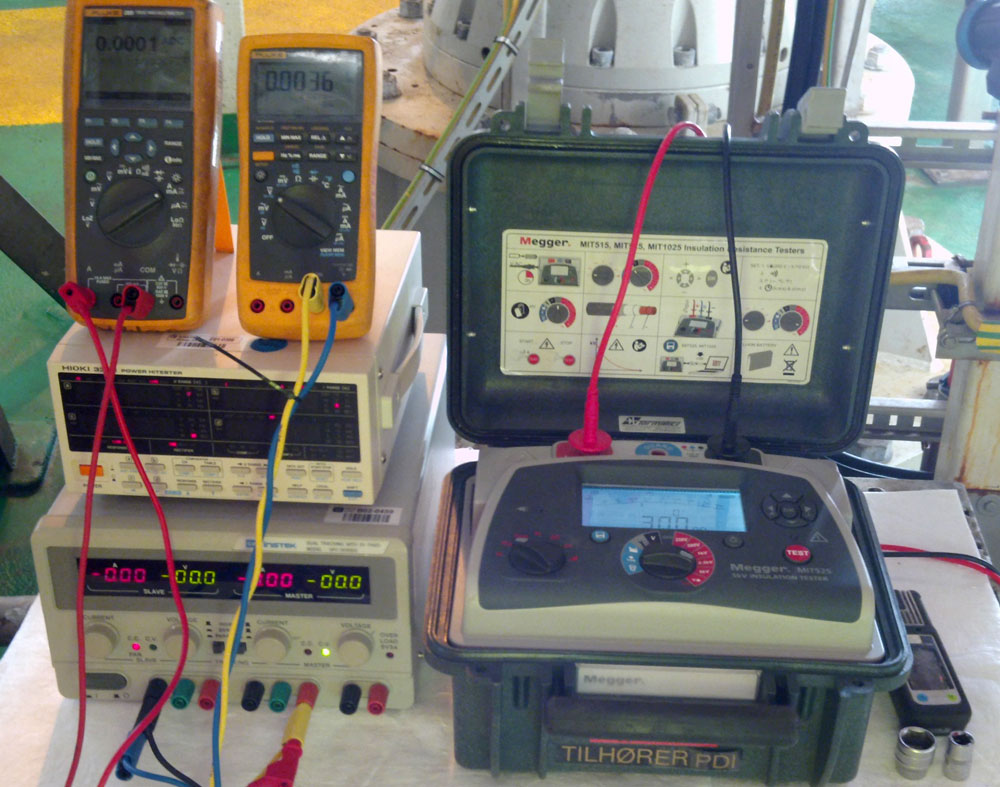
When the insulation resistance falls below acceptable levels, or when a fault is detected by the fault detection systems, immediate action is required. Verification of the fault could be done by a separate insulation resistance measurement and/or with high voltage VLF (very low frequency) testing, when required.
Locate Faults
Based on the insulation resistance level, several non-destructive tests are appropriate to locate faults. Faults are normally of such complexity that relying on one test method is seldom sufficient. Various fault types (phase-ground or phase-phase) and end connections (insulation plug, step-down transformer, etc.) benefit different measurement methods. Locating faults can be very complex if a fault occurs on a line with multiple degraded connections.

- Fault Classification
The loop (phase-phase) and insulation (phase-ground) resistance and impedance (only AC) will quickly give valuable overview of the system. Documents from FAT, fingerprints from commissioning or numerical calculations can be used as reference for comparison to the measured values. For low resistance faults, the measurements may in some situations give good estimations of the fault location. - Time Domain Reflectometer
A Time Domain Reflectometer (TDR) is a convenient tool to find low resistance faults between phases or between phases and ground. A voltage pulse is applied to the cable and a signal is reflected whenever it passes a relative change in the cable wave impedance. The distance to the fault is given by the cable impedance and time for the pulse to return. For best accuracy, TDR fingerprints should be recorded at installation of the cables. On conventional screened cables, the range can exceed 100 km. - Wheatstone Bridge
A Wheatstone Bridge may be the most accurate instrument for locating cable faults, especially for fault in the high resistance range (MΩ). It is operated by balancing the faulty cable system to well-defined resistances in the bridge. To operate the bridge, the cable ends must be looped. The bridge can only pin-point one fault, reducing the accuracy in cases of degraded insulation resistance at multiple locations. - ROV Operation
Depending on the cable fault complexity, ROV operation may be required. By sectioning the cable (if wet-mate connectors are available), or changing connection plug in the inaccessible cable end (short-circuit or isolation plug), even the most complex faults could be located.
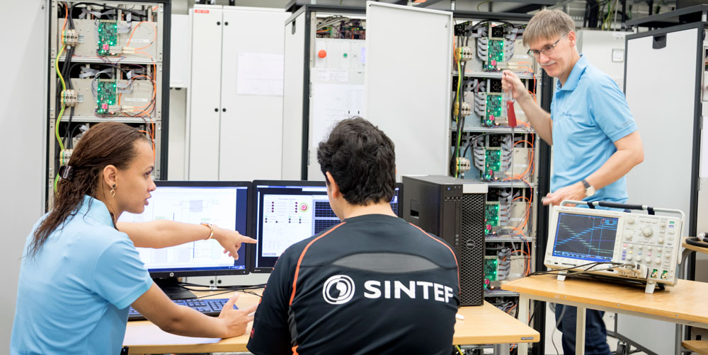
Long Experience
For several decades, SINTEF has participated in research and development projects of all kinds of electrical equipment for the Norwegian oil and gas business.
SINTEF has world-leading laboratory facilities and top-level expertise, supporting customers with studies of single components or huge innovation projects. For fault detection, fault location and condition monitoring, experienced crew and dedicated equipment is available for challenges word-wide.


Comments
What is electrical wire?
Electrical Wires are single electrical conductors, while cables are multiple conductors that have been encased in the sheathing.
Most wires are made of copper or aluminum, but they can also be made of steel. They may be bare or insulated, and they’re typically covered in a thin layer of PVC. If they have a PVC sheath, then the PVC is colored to indicate whether the wire is a neutral, ground, or hot wire in your electrical installation. We discuss wire colors in their own section in this guide.
Cables contain at least a neutral wire, ground wire, and hot wire that are twisted or bonded together. Depending on its purpose, the cable may contain more wires. The wires in a cable are insulated in their own color-coded layer of PVC. The group of wires is then encased in an outer sheath to make up the single cable!
Hi Hans,
Thank you for your comment. If the fault is low resistance, TDR may be convenient. Two such instruments are Megger Teleflex SX-1 and Megger Teleflex VX. If the fault is unstable, Megger Surgeflex can be used in addition. If the fault is high resistance, a measurement bridge may be more appropriate, such as Megger HVB 10. All of these instruments can locate the fault within a few meters.
If you need any further assistance, please find my contact details below the article.
Many power companies in China are developing offshore wind farms. Due to the limitation of experience and cable lay equipment, some potential faults have occurred in the laying process of submarine power cables, and it is an urgent problem to accurately locate the fault points in the maintenance process of cables. Customers in China are hoping to locate faulty cables buried on the seabed within a few meters.
If you and your team can provide such requested solution?
In fact we use lira technology from Norway and it can do the location quickly within a few meters