However, in an integrated and interdependent cyber-physical system, new threats appear which must be understood and dealt with. Of particular concern and interest are the causes of an inconsistent view between the physical power grid (PG) and the ICT system (Distribution Management System-DMS).
The novelty introduced in this blogpost, and the article it is based on, is its focus on the dependability of a smart distribution grid (SDG), operated by the support of an advanced surveillance and control system with distributed sensors and controllers. The main objective is to investigate the causes of inconsistencies between the state of PG and the state view in the DMS, and to propose a modelling approach for their assessment.
Read more: Learn more about the future power distribution grid at CINELDI: The Centre for Intelligent Electricity Distribution. CINELDI is a research centre working towards digitalising and modernising the electricity distribution grid for higher efficiency, flexibility and resilience.
The integrated ICT and PG system studied in this paper is defined to include the DMS, the data communication network, the software in the IEDs, and physical elements in the power grid (e.g., breakers, power lines, disconnectors).
Why do we need to assess the inconsistencies between DMS view and IED state?
The DMS depends on a correct view of the state of physical devices (and power flows and voltage quality). Correct state view is crucial in order for the controller to trigger the correct action and to change the state of the electric grid when needed, as well as for the human operators to correctly assess the state of the grid.

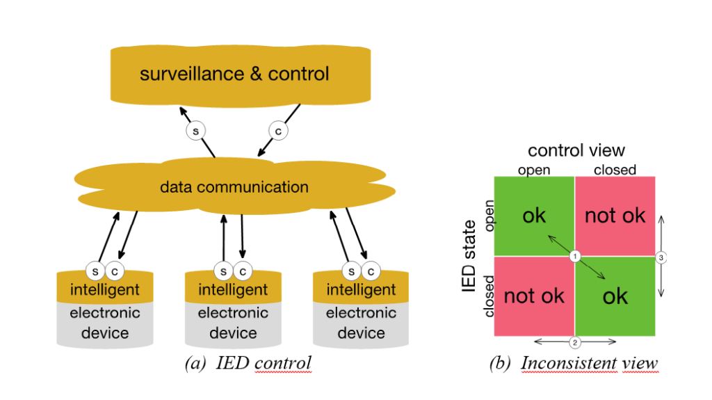
In Figure 1(a) a principle sketch of the system considered in this case is given. Intelligent electronic devices (IEDs) are assumed to contain sensors (s) and a controller (c), which are interconnected and also connected to a surveillance and control system via a data communication network. E.g., the state of the electronic device is observed by a sensor. The signal is sent via the data communication network to the surveillance and control system, which processes it and decides whether actions need to be taken to change the state of the electronic device (or other actions to restore power supply, regulate voltage, change the power flow). An appropriate control message is then sent to the IED via the same data communication network.
Read more:
Figure 1(b) shows an example of inconsistencies (in red) between the surveillance and control view and the state of, e.g., a physical disconnector position of an IED. The disconnector can be closed, while the surveillance and control system believes it is open, and vice versa.
Taxonomy for evaluation of Smart Distribution Grids
We introduce the necessary terminology to describe the causes of failures in such an integrated system, and the consequences of inconsistencies between ICT view and PG state.
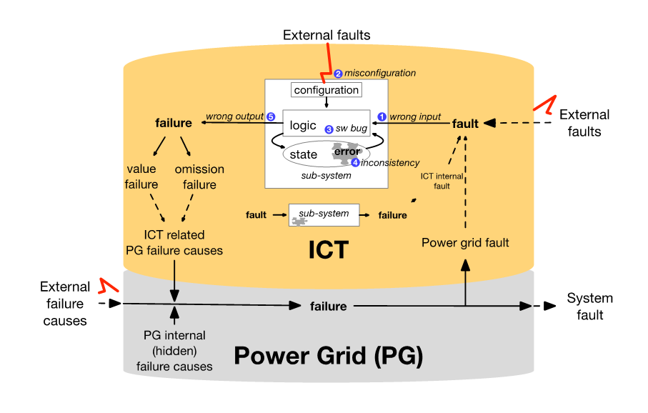
Most software in today’s ICT systems is continuously operating and has an internal state which is maintained across several inputs (e.g., sensor data, controller commands). Examples of such systems are surveillance and control systems, and the software logic in IEDs in the power grid. The subsystem in the ICT part of Figure 2 is using what is referred to as a Moore/Mealy model to describe the failure mechanisms relevant to the software that we have modelled. In a Moore/Mealy model, any combination of a wrong input signal (e.g., sensor data) (denoted (1) in blue), a misconfiguration (2), or a faulty logic of the software (3), will introduce an error in the state space of the software, e.g., an inconsistency (4) in the data of the system. This will again lead to a wrong output signal (5) (e.g., a control command). Note that the fault activation may be conditioned by a specific (set of) internal states of the software, and hence, it is the combination of the internal state and the input signal, logic, and configuration, which causes the fault activation.

Failure causes classification for SDGs
A large number of different failure causes (denoted faults in the ICT terminology) will affect different parts of the system in Figure 1(a). In Norway, the failure cause classification is standardized and faults are reported in the Norwegian data management system, FASIT. In a combined ICT and Power Grid system, alternative classifications of failure causes apply, and in this blogpost we use external and internal failure causes.
External failure causes: environment (weather-related causes), operating stresses (stresses above critical level, e.g., excessive load of ICT system), human errors performed by people outside of the organization:
- intended (malicious attack and intrusion)
- unintended
Did you know? Environment causes account for approximately 50% of the failures in the Norwegian distribution grid 1-22 kV. The major weather-related causes are wind, vegetation and lightning.
Internal failure causes: related to components themselves or the grid or telecom operator. It includes internal fault in an equipment (e.g. a stuck disconnector), or interaction or operational mistakes, accidentally made by staff or hired personnel that are operating or maintaining a system.
These failure causes are leading to:
- Permanent (solid, persistent) – fault will remain unless it is removed by some intervention.
- Transient (present short time) – fault disappears without intervention. A transient fault for instance on a power line will disappear after an automatic reclosure of the circuit breaker.
- Intermittent faults (comes and goes) – transient fault that recurs. It can develop into a permanent fault, e.g., a crack in an insulator that result in flash-over in damp weather.
Design (logical) faults are human made faults during specification, design and implementation of hardware and software. Software faults are commonly referred to as bugs, and are logical mistakes or inadequacy during specification design or development, or dynamics in the deployed software processes described in the Moore/Mealy model above.
Modelling Information Inconsistencies
To illustrate and assess the causes of information inconsistencies, a modelling approach is taken. The behavior of the model is as described below:
- Disconnectors may not switch on command (physically stuck or software fault).
- Disconnectors can switch without command (software fault).
- Sensors can send wrong value, no value or delay value.
- Communication system can be down when needed (equipment failure, congestion, bad radio link).
To study the effects of the physical disconnector faults, sensor and communication faults, and software bugs in the DMS, a simulation study is conducted for measuring the information inconsistencies between the DMS view and the IED state. The metric that is used is sensing inconsistency, which is the (stationary) probability that the observed state of a device deviates from the real state of the same device.
Read more: Learn more about the future power distribution grid at CINELDI: The Centre for Intelligent Electricity Distribution. CINELDI is a research centre working towards digitalising and modernising the electricity distribution grid for higher efficiency, flexibility and resilience.
As systems generally can be made more reliable by investing (wisely) more money, one use of this model can be to evaluate how reliable the sensors need to be to ensure a given probability of consistent information.
The study has shown the direct and high impact of value failures, i.e., sensor or controller data which are valid but wrong. We have also observed that software bugs in the DMS, have minor effect on inconsistency if continuous disconnector status updates are received. The model is flexible and can be scaled up to assess systems consisting of several IEDs, and add different failure modes and causes.


Comments
No comments yet. Be the first to comment!