Digital twins replicate a physical system by a digital model that is fed with real-time data from site. Among several uses, the digital twin can be used to estimate the state of the system’s health and then act upon that information. This means it is now possible for condition-based maintenance to be a successful maintenance strategy choice. Recent research puts us one step closer to implementing digital twins for power electronic converter systems.
Maintenance by time
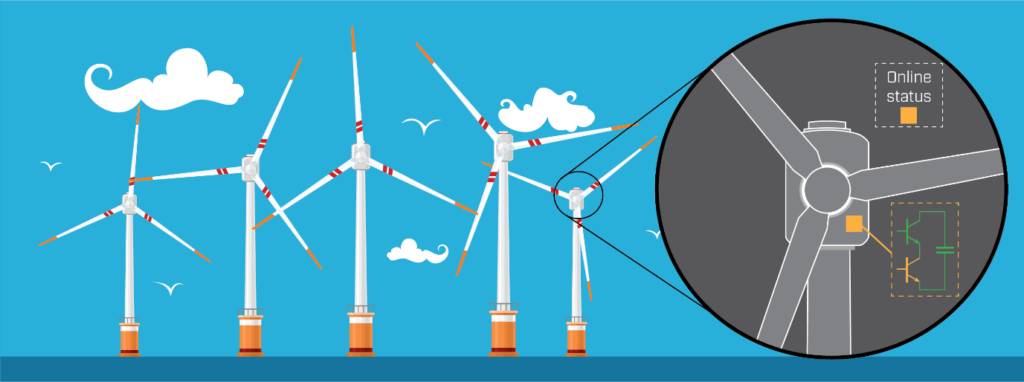
Imagine being the operator of several aged wind farms. Inside the nacelle of each wind turbine, a power electronic converter enables the export of power from the wind to the grid and the users. The converter is not easily accessible, so inspection and repairs are complicated and costly. Today, the operator is blind regarding the health of the power converter inside each turbine. If it fails, the turbine is unable to produce until the maintenance operation has been planned and completed.
If the operator had access to a health estimation, he or she could plan the maintenance action beforehand and stop the turbine for only the time it takes to perform the tasks. In total, the wind farm operator obtains lower risk and lower losses due to the digital twin monitoring.
Interval-based maintenance is the chosen strategy of many products. Many of us are used to painting our house every 10 years or driving the car to the garage to change engine oil every 15 000 km. This is the preferred choice when it is difficult to assess the current state, e.g. how is the paint or my engine oil doing today? For power electronic converters, the case is similar.
Digital twins allow condition-based maintenance
Our current research shows promise for health monitoring of power electronic converter systems by using digital twins. Having a digital twin of these critical systems expand our capabilities of what can be monitored and how precisely it can be done.
A digital twin is defined as a digital replica of a living or non-living physical entity. One example is a model of wind turbine or the engine room of an electric ferry, where measurements from the actual turbine or vessel are transferred to the digital model and calculated into component stress. Such stress is not directly measurable. However, we can digitally replicate such inaccessible measurements. Combined with selected algorithms and models, we can make an online estimation of the health of the system. Now, the maintenance can be scheduled before a potential failure and only when the equipment is nearing its actually end-of-life. As a result, condition-based maintenance strategies can be successfully expanded to power electronic systems.
Estimating lifetime in real-time
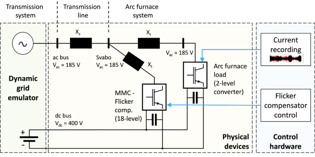
A system for real-time lifetime estimation was demonstrated in the ReliPE project (Reliability and Ruggedness of High Power, High Voltage Power Electronics). A flicker compensator experiment was implemented in the National Smart Grid Laboratory. Its mission was to improve the power quality at the grid connection of an arc furnace load – a highly nonlinear and fluctuating load. Another converter was provided with control for emulating the flicker load.
A condition-monitoring system was implemented on one converter module in multi modular converter acting as the flicker compensator. The system performed real-time condition estimation of a critical hotspot and lifetime estimation during operation. Results showed that the hardware and developed software solution could successfully operate in real-time. At the same time, it showed that such a flicker compensator is a tough load on a converter due to a lot thermal cycling compared to other industrial applications.
How a digital twin works
How is it done in more detail? Using data and simulators, the digital twin enables monitoring, optimization, prediction, and improved decision making. In manufacturing, a digital twin might be used to optimise and plan future production. For power electronics, the main functionality is an online estimate of the remaining expected lifetime for each vulnerable converter component.
For such components, the usage leads to stress that deteriorates the component. This stress is cumulative and eventually leads to a component failure. To obtain the health estimate, the system has to continuously measure the usage of the component, e.g. a power electronic switch. Using a physics-based model, the usage is calculated into stress on the switch. Finally, combining the cumulative stress with lifetime models, we are able to estimate the remaining lifetime of the component.
When the remaining health goes low, the owner gets a warning that it would be beneficial to plan for maintenance soon. Hence, the downtime can be short and planned instead of having to wait for the right parts, personnel, and availability. This leads to economical savings for the system owner.
Improving the health estimation
The lifetime estimation technique is well established in the research community. However, not having feedback in the estimation algorithm leads to larger uncertainties. To further improve the health monitoring capabilities, additional hardware can be installed on-site that monitors specific parameters of the converter that we know are sensitive to ageing.
Examples include the forward voltage drop of a semiconductor, thermal resistance of the power module and leakage current.
If we keep a close eye on such parameters, we can get additional information about the age of the equipment. Other components of the converter could also be monitored, e.g. the electrical and thermal conditions of dc-link capacitors.
Lifetime estimation of power semiconductors
Using lifetime models of power semiconductors allows us to design and estimate that a power electronic converter can last for the duration required by the application, e.g. 15 years in a wind turbine.
To construct a lifetime model, detailed knowledge of the component and how it is used is needed. The lifetime is the number of degrading cycles or time that it takes before the device fails. Hence, the lifetime model must take possible failure mechanism into consideration. There can be more than one, and usually the most prominent are targeted.
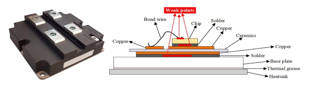
For a power module in a power electronic converter, mechanical connections are most prone to wear over time. The bond wire connection to the top of the chip or the solder layer between the chip and the copper layer sustain thermomechanical stress each time the power module is heated and cooled down. This comes from a difference in coefficient of thermal expansion (CTE) of different materials used. Each thermal cycle, the different expansion puts strain on the connection.
Over time, this strain leads to cracking and faults in the connection point, until one day the connection is completely lost. This constitutes the aging process of the device. Usually, the cracking phenomenon will lead to increased losses in the converter which further accelerates the aging process.
Lifetime model from accelerated testing
In the lifetime model of a power module, the temperature swing of the semiconductor chip junction is used as the main aging parameter. Existing lifetime models for power modules are represented by a formula that relates number of temperature swings and other stress variables to operational parameters. From accelerated aging tests, the correlations between stress variables and lifetime of a component can be tested in a laboratory setting, and the lifetime model parameters are calculated.
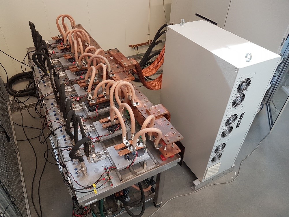
At SINTEF Energy, we have a setup for accelerated testing that is capable of simultaneously testing up to 8 units with a load current up to 2000 A. An additional result of the ReliPE project is validation of the lifetime models, in particular, at low temperature swings around 30 K as well as combinations of high and low temperature cycling.
From measurement to lifetime
An algorithm is needed to translate the on-site measurements to the thermal cycles. In addition, a system is needed for adding up each identified stress element over the lifetime of the device.
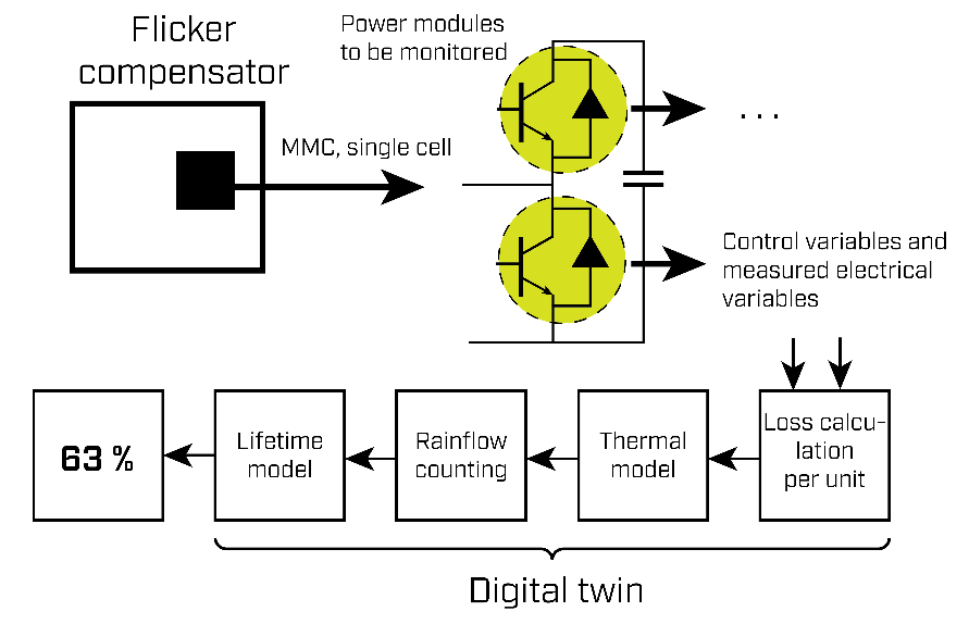
An overview of this system is shown in Fig.5. For the first part, an electrical and thermal model of the converter is used. The thermal cycles are extracted using the Rainflow counting algorithm. These are fed to the lifetime model to calculate the lifetime that was consumed by each cycle. All cycles are combined using Miner’s rule.
Finally, the remaining lifetime of the monitored component, or the state-of-health, is reported. Hence, the digital twin connects the measurement from the real system to the estimated remaining lifetime.
This number can be used by operators to make better decisions and better optimise their systems. The next step is to integrate such a system in an industrial application and SINTEF Energy is currently in dialogue with industrial actors to demonstrate the technology.
Read more about the implementation of real-time Rainflow counting
I am intersted in digital twin