
There are several technologies and methods available for electrical heating of subsea flowlines for the oil and gas industry. In this overview, we will take a look at each of the different technologies and point out their way of operation, advantages and disadvantages.
SINTEF has provided consultancy and research services of all these heating methods since the 1980s and has been involved in most of the field developments world-wide, from pre-studies to commissioning, fault detection and repair.
Why electrical heating of subsea flowlines?
The mixture of oil, gas and other substances in the flowlines need to be maintained at elevated temperatures to prevent wax and hydrates from causing blockages in the flowline. These problems are particularly evident during a prolonged system shutdown, when there are no‐flow conditions and the flowline from the well cools to that of the surrounding sea temperature.
You might also find this interesting
- You might also find this interesting: Red mud – an unnecessary problem?
Process engineers provide several solutions to prevent the formation of hydrates during production. The traditional method has been injecting chemicals (e.g. methanol) in the well stream at the well head or manifold, to lower the formation temperature of hydrates.
By heating the flowline electrically, the need for chemical injection is reduced considerably. Electrical heating is proved to be very suitable for short as well as long flowlines since heat can be generated evenly along the whole length. The various heating options are expected to be deployed increasingly as an elegant technical solution to optimize the flow assurance management during production flowline’s service life. Electrical heating is an environmentally friendly, cost-saving solution, bringing significant reduction of projects overall CAPEX and OPEX.
Induction heating of subsea flowlines (cable)
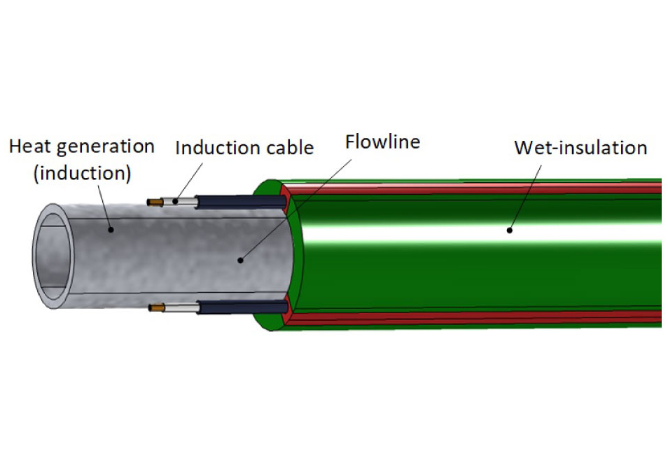
The first electrical heating method that SINTEF contributed to was induction heating. As a part of an industry project with Equinor, Nexans and SINTEF, the system was verified during autumn 1991 and later qualified. The system was named ITTI (Induction Through Thermal Insulation). Two or three power cables were placed in groove cuts in the wet insulation and were evenly distributed around the flowline circumference. By applying an electrical current in the cables, single-phase or three-phase, heat is generated in the flowline steel due to electromagnetic induction.
The system was never installed in full-scale, mainly because of production complexity (production of insulation with groove cuts) and cable costs (power cable length is two-three times the flowline length).
As an alternative, it was evaluated to place the power cables outside the insulation. However, this was not considered feasible since the efficiency decreases greatly when increasing the spacing between the cables and flowlines. In addition, a mechanical structure for alignment of the cables would be needed.
Induction heating of subsea flowlines (coil)
Induction heating by insulated coils is the electrical technology which can deliver highest power per distance. The main applications are usually shorter length, like heating of topside pipes or in cold flow technologies. This is due to the large amount of cable which often is required. In cold flow technologies, the fluid may be cooled to wax formation temperatures in a controlled manner, letting wax form on the pipe inner wall. When applying high power through coils wrapped around the flowline, the deposit will separate from the pipe wall and be transported with rest of the bulk flow.
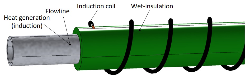
The main advantage of the induction system is the possibility to heat flowlines with huge power requirements, 3-4 kW/m. Lengths are often modest, a few hundred meters, making the total power requirement lower than other heating methods. Dedicated high voltage cables are required for lengths of a few kilometres with moderate power requirement.
Direct Electrical Heating (wet insulated flowlines)
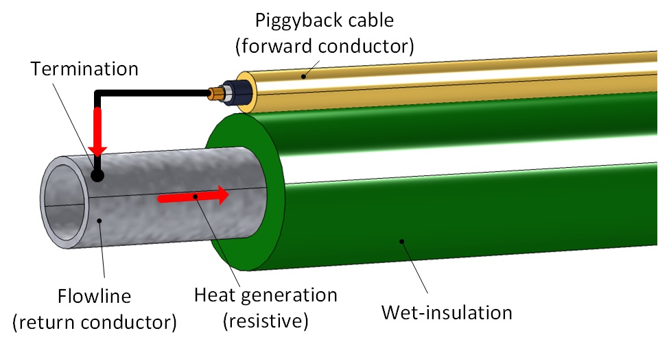
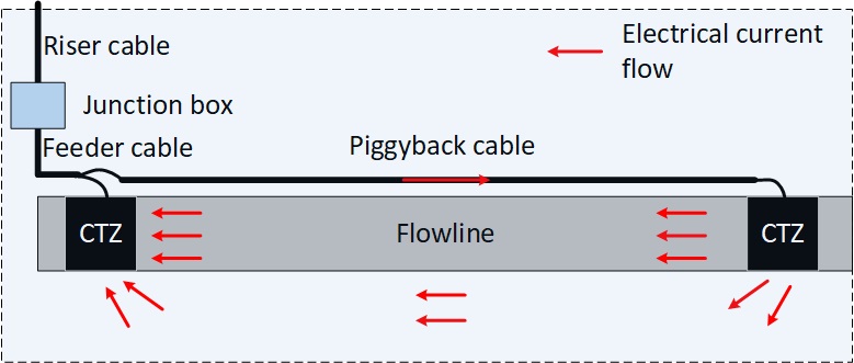
During qualification of the induction system ITTI, it was discovered that the heating system would improve greatly by applying the alternating current (50/60 Hz) directly through the steel wall. Instead of multiple power cables in groove cuts, one power cable could be piggybacked to the flowline. A power cable is connected at each end of the flowline, forcing the electric current through the flowline steel, generating heat. This discovery was later named Direct Electrical Heating (DEH) and is the most common electrical flowline system to date. DEH was qualified in a joint industry project with Equinor, TechnipFMC, Nexans, and SINTEF in the mid-90s.
The first DEH system in operation was at the Åsgard field in the year 2000. Today, 16 fields have flowlines with DEH. These are located outside the coast of Norway (Åsgard, Alve, Goliat, Gullfaks Sør, Huldra, Kristin, Maria, Morvin, Norne, Skarv, Skuld and Tyrihans), West Africa (Lanzi and Olowi) and the Caspian Sea (Shah Deniz).
Tyrihans is the installation with the highest voltage (52 kV), current level (1600 A) and largest flowline dimension (18”). The deepest (1050 m) and longest (43 km) flowline is in the Lianzi field. The Ormen Lange field has a flowline which can be retrofitted with DEH, with a rated current of 3000 A, voltage level of 52 kV, and U-value of 20 W/m2K.
The DEH technology itself is not patented, giving room for multiple vendors. Currently, the only two vendors of cables and ancillaries are Nexans and Aker Solutions, who have patens for equipment design. The installation contractors to date are TechnipFMC, Subsea7 and Saipem.
DEH is an external part of the flowline, making repair and inspection possible. There have been two known failures in the system, at Huldra and Skarv, both caused during installation. The DEH systems were successfully repaired. The design was modified to avoid similar failures in the future.
For safety and reliability reasons, the electrical system is grounded to seawater. It is not considered feasible to electrically insulate a flowline with wet-insulation throughout its lifetime. This has implications with respect to anode requirements, interference and efficiency.
Around 40 % of the electrical currents are conducted by the seawater. This means that up to several hundred amps needs to be grounded to seawater by anodes. Most of the anodes are located in a 30-50 m section around the termination plates and prevent corrosion on the flowline. No issues on installed fields have been communicated with respect to AC corrosion on the flowlines or high anodes consumption. Adjacent and parallel equipment may be exposed to electromagnetic induction, meaning that some additional anodes must be installed on these elements.
The electrical currents in the seawater contribute to 5-10 % of the total losses and losses in the power cables to 20-30%. This means that the DEH system has around 60-70 % efficiency. For a buried flowline, with the power cable beneath, the efficiency can reach up to 80-90 %.
For simplicity, the DEH power system frequency is 50 or 60 Hz, equal to the topside power supply. For flowlines with lengths less than about 60 km, it may be beneficial to increase the power frequency to 100-200 Hz. Increased power frequency may reduce the supply current and power demand, hence the size of the electrical components (e.g. riser, feeder and piggyback cable). DEH is also considered for flowline lengths of 200-250 km. To reach such long ranges, lower power frequencies (15-35 Hz) are required. Lengths of about 150 km may be reached at 50 Hz with mid-point termination.
The heat development in the flowline is influenced by its electrical and magnetic properties, which varies from different manufacturers, steel grades and coating facilities. Other factors affecting the power rating are pipe dimensions, insulation level, ambient temperature, hydrate formation temperature and required heating time.
Direct Electrical Heating (pipe-in-pipe)
Following the DEH success, a similar electrical heating system was introduced to the offshore flowline marked; pipe-in-pipe (PiP) direct electrical heating, also called closed DEH-system. There have been several individual studies of this heating system but only a few installations exist. Shell has three installations in the Golf of Mexico (Habanero, NaKika and Serrano/Oregano), all installed in the early 2000s with lengths up to 13 km. The flowlines are split into shorter segments that are heated individually.
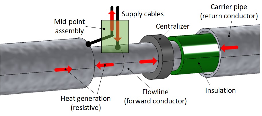
The main advantage with the PiP system is that the current path is clearly defined. The high voltage cable is connected to the production pipe via an electrical connector at the mid-point assembly. The electrical current is then conducted by the pipe wall to each end of the flowline section, where jumpers connect the production pipe to the outer pipe.
At the outer pipe, the voltage is near zero. Only half the feeder cable length is required compared to DEH since the connection is at the mid-point. However, in contrast to DEH, the feeder cable to the PiP-system require two conductors. The piggyback cable in a DEH system only require one, as the flowline act as return conductor.
Since the PiP-system has excellent thermal insulation (low U-value) the heat requirement is low. The efficiency, however, is not very different from DEH systems since a considerably part of the heat is developed in the outer pipe.
What makes the PiP-system complex is that the production flowline (at least for supply voltages above 3-6 kV) should be made similar as high voltage power cables. This is extruded high-quality electrical insulation around the production pipe, followed by a thin semi-conductive layer, a purity free annulus and semi-conductive centralisers to safely conduct capacitive charging currents to ground. The major disadvantage is that the most vulnerable electrical component, the mid-line electrical connector, is not reparable.
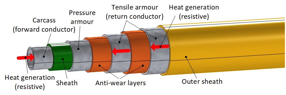
Electrical heated flexible pipes work similarly as the PiP-systems. A current may be applied to the carcass and returned through the tensile armour layer. Heat is generated in the metallic elements from resistive losses. The main advantage is that the electrical connections are topside, eliminating the need for subsea connections.
Some installations with such systems are projected, but the operation experience is unknown by the authors. The length is typically limited to a few kilometres to reduce requirements with respect to high voltage systems. The most critical component (apart from production process, installation etc.) may be in the ends where leakage currents and conductive boring fluids can degrade fittings.
Heat Tracing in subsea flowlines
Heat tracing is the latest technology to be installed in subsea flowlines. The heat trace cables are placed around the production pipe in a PiP-system. There are a few different designs available, but the most common is to have several three-phase heating cable circuits. A 6 km pilot was installed for the Islay project around 2012. By 2021, two projects are scheduled in the North Sea. These are Ærfugl (20 km) and Fenja (36 km), each manufactured by different vendors.
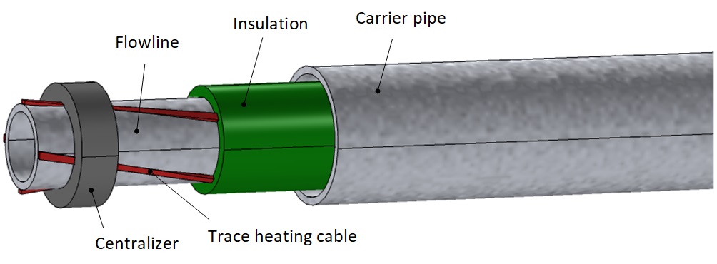
The main advantage of the heat trace system appears to be the high efficiency (>90%). Heat is developed close to the production pipe and the PiP-design has excellent thermal insulation. The heat trace cables require proper electrical insulation (6.6 kV used for the Fenja project).
The main disadvantage is the reparability of the system. As the heat trace cables are placed within the carrier pipe, access is limited. Electrical breakdown of the power cables themselves are not considered likely, but the many joints of the heat trace cables are of concern. As in other cable systems, joints and external impacts are the main reason for failure. The number of joints vary from vendors. In some designs, there are electrical joints for each pipe joint (12-24 m), in others pr. kilometre. For a 30 km heat trace system with 12 heat trace cables (4 phases), there are 360 electrical joints. One failure in one joint will make an entire three-phase circuit defect.
Summary
Different heating systems for subsea flowlines have been evaluated. The main advantages and disadvantages are given below.
| Heating method | Main advantages | Main disadvantage |
| Induction Heating | · High power output· Simple design
· Low U-value requirement | · No installations subsea· Long cables needed |
| Direct Electrical Heating(wet insulated flowlines) | · Field proven (16 fields) since year 2000· Low U-value requirement
· Reparable (field proven) · Reeling and S-lay · Good operation experience · Wet insulation | · Efficiency 60-90 %· Considerable topside equipment
· Anode system · Induction interference · No redundancy |
| Direct Electrical Heating(pipe-in-pipe) | · Low heat requirement | · Efficiency 60-80 %· Complex manufacturing
· Complex design of key components mid-line · Limited field installations · No redundancy · Expensive pipe system |
| Heat tracing(pipe-in-pipe) | · High efficiency (90-95%)· Low heat requirement
· Redundancy (up to 300%) · Low electrical stress on cables | · Little operation experience· Extensive amount of electrical joints
· Main components not reparable · Limited to reeling · Expensive pipe system |
An overview of our consultancy and research services for Direct Electrical Heating (wet insulation) can be found here. We also provide services for all other heating concepts.


Comments
Thank you for sharing information on efficient electrical heating technologies for ensuring the flow lines. This blog evaluates various heating systems flow lines, outlining their main advantages and disadvantages.
Hi Torsten,我个人还是倾向于集肤效应加热方式,集肤效应安全可靠,本人已经试验过多条集肤效应加热。
Hey, I read your article and your information is very amazing and so much helpful for me. Keep it up and Thank you very much.:)
DEH requires Water in the Line to Load Test before dewatering, what is the ETH electrical testing sequence to set up the Control System when Offshore before staring Hydrocarbon Production
Hei,
this is a nice overview and giving some insight – thanks.
A question – have you also looked into Skin-Effect Heat Tracing Systems?
From theoretical Point of view it Looks promising, but I haven’t seen any subsea application – yet.
Hi Torsten,
We have also looked at skin-effect heat trace systems. The way of operation is similar to regular heat tracing cables; heat is developed in conductors when conducting an electrical current (commercials claim it to be more sophisticated than it really is). A difference is that the return current is conducted by a steel tube surrounding the supply cable. Thus, only one component is needed, in difference to heat tracing systems which often consist of sets of three cables (which may be placed in a common sheath). Most of the heat is developed in the tube, which is favourable with respect to temperature in the inner cable insulation. Power factor can typically be 0.7-0.8 (depending on tube thickness), much lower than the resistive heat tracing systems.
In subsea applications, more than one skin-effect system may be needed at each flowline to produce enough heat (without thermally overloading the high voltage insulation) and to obtain redundancy. Since the heat is generated in one place, the thermal requirements to the high voltage insulation may be very high. I think the main reason for the absence in subsea applications is the complex installation. The tube is often welded to the flowline, which is time intensive, at least if performed at the installation vessel. In addition, heat efficiency is less than for heat tracing (much of the heat never reaches the flowline).
Great article! As oil and gas explorations move towards impossible environments such as longer subsea tie-backs, operators face challenges of flow assurance in deep sea. DEH technology is being widely used nowadays in place of traditional systems of pressure evacuation and use of chemicals.
Dear Jonathan,
You are right! We have performed studies indicating that DEH can also be used on flowlines up to around 150 km at 50 Hzby using mid-point termination (instead of termination in the end). In reality, a 150 km mid-point system can be considered as 2×75 km DEH-systems. At reduced power frequency, the system can reach 200-250 km (or twice the length with mid-point termination).
Dear Lervik,
DEH is the most feasible heating method for your system and is field proven for 1000 m depths. Induction heating is not yet field proven and is (generally) more costly.
Which system will you recommend for a 60 km 12″ pipeline with a U-value of 5 W/mK (wet insulation) at 1000 m water depth and a heat input to the steel pipe of 120 W/m?
Dear Lervik,
DEH is the most feasible heating method for your installation and is field proven for 1000 m depths. Induction heating is not field proven and is (generally) more costly.