Authors: Pierre Cerasi, Jelena Todorovic, Anna Stroisz, Hossain Bhuiyan, Nils Opedal, Nicolaine Agofack and Laura Edvarsen

Portland cement is the most common material used in the construction and plugging of wells – however, cement bond to other materials is the weakest link in the well’s integrity. At the Norwegian CCS Research Centre (NCCS), new methods have been developed to measure bond strength, as well as evaluate them under more realistic field conditions.
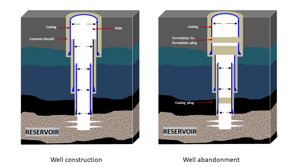
Cement plays a critical role in ensuring well integrity. It is routinely used in well construction, where its role is to strengthen the borehole so that it cannot collapse and cut access to fluids that need to be injected into or produced from a subsurface reservoir. Another role is to isolate the well from porous rock formations and fluids at different depths, as they could mix with the fluids transported in the well and accidentally contaminate shallow water layers or even come all the way to surface. In the context of CO2 storage, this breach of isolation would also potentially compromise the containment of the CO2 in its intended reservoir. Well integrity research deals with identifying, qualifying and remediating barrier breaches that are susceptible to arise in subsurface wells or their immediate vicinity. Portland cement is the most widely used material for both constructing wells and plugging them after they have ceased to be used. Experience from the last 20 years shows that the weakest link in well integrity related to cement lies in the cement bond to other materials, be it the well steel tubing (casing) or the rock formations into which the well is drilled. Previous research has focused more on the mechanical properties of cement itself than on the means of measuring cement bond strength in terms of resistance to shear. At NCCS, new methods have been devised to also measure the more elusive, but potentially more critical, tensile bond strength, as well as evaluate them and other properties under more realistic field conditions. These include the temperature, rock formation type, confining stresses, cement additives commonly used in the oil and gas industry, and not least, exposure to CO2.
The role of cement in subsurface wells
Portland cement, similar to the paste mixed with aggregates to produce construction concrete, is widely used in subsurface wells, most notably oil and gas production wells. Similar wells are drilled for CO2 injection, and potential storage sites could be chosen in or near abandoned oilfields, where old, plugged wells are abundant. The cement construction in all these wells is either in the form of thin, long sheaths that effectively consolidate the concentric metal tubulars forming the well and secure them to the rock formations outside, or solid plugs that cover the whole wellbore diameter. These last plugs are placed at the end of the well’s life prior to abandonment as a security feature to ensure that no underground fluid is able to migrate up the abandoned well. Such a leakage would potentially threaten shallower aquifers or pollute the sea with hydrocarbon residues or heavy metals from well fluids or deeper porous formation brines. Thus, cement plays a dual role in well construction: holding together the telescopic well structure by gluing it to the outside rock face at discrete intervals, while at the same time providing a barrier to the migration of unwanted fluids from porous formations to the well and back to shallower formations or the topside of the well.
To avoid breaches in this cement barrier, the mechanical and hydraulic properties of the cement bulk must be sufficiently strong and impermeable so as to withstand any solicitation throughout the well’s active life and post abandonment (when it is plugged with cement). These solicitations occur in the form of stresses and fluid pressure. The stresses arise as a function of either differential pressure between the borehole and fluid pressure in the rock formations around the well, or as a result of temperature contrasts between the well fluid and pore fluid in the formations. As a result of such contrasts, the different adjacent materials,, rock, cement and steel will expand differently, and thereby risk creating fractures in the material least able to deform or at the interface between two materials.
Methods for testing cement strength
The bulk properties of cement can be routinely tested by curing small cylindrical plugs, which are then subjected to compression tests in a load frame. By bringing axial pistons that are in contact with the end faces of the cement cylinders closer together, we achieve increasing compression in the cement bulk. Eventually, the resistance of the cement to shear forces is overcome, and the plug brakes along a diagonal fracture plane. This produces a way of measuring the unconfined compressive strength. Similarly, compressing a thin cement disk specimen by using the pistons to press together two contact points on the circumference along a diameter of the disk results in the disk splitting more or less along the same diameter. This is an indirect method of measuring the tensile strength of the cement bulk.
These tests are routinely carried out at SINTEF for different cement formulations used in well construction. Exposure of the plugs to CO2-brine mixtures has shown that very little changes can be expected, as the intact cement is quite impermeable, although reactive to the fluid. Leaching tends to fragilise the cement, while further chemical reactions result in the precipitation of carbonates, which seems to restrengthen the cement.
Cement bond strength
Even though the bulk strength of cement is high, the same cannot be said for its bonding strength to different materials. One of the reasons for poor bond strength is the tendency of cement to shrink while curing, thereby retracting from its initial good contact with surrounding materials. To some extent, this can be counteracted by incorporating chemical additives into the cement paste. In addition, the hardening reaction happens when the cement powder hydrates: in other words, it needs a certain amount of water to cure. At the interface, the water availability may be different depending on the neighbouring material. For a well, this material can be steel casing, which results in very poor bonding, or a porous rock with a water-bearing pore structure. If that rock has large, open pores, i.e. it is very permeable, it will facilitate water exchange with the cement and produce good bonding results. However, shaley formations, which are almost impermeable, produce very poor bonding results. The bonding is also a function of compressive stress conditions, which will vary depending on the depth at which the cement sheath or plug is placed, with better bonding for high stress conditions.
Innovative testing at SINTEF
To take into account the field conditions mentioned above, several innovative techniques were developed at SINTEF as part of research performed at the BIGCCS centre (one of the precursor centres for environmentally friendly energy in Norway before NCCS) and the DrillWell SFI (centre for research-driven innovation). These techniques were further developed in the current NCCS centre.
Pushout test with mud contamination
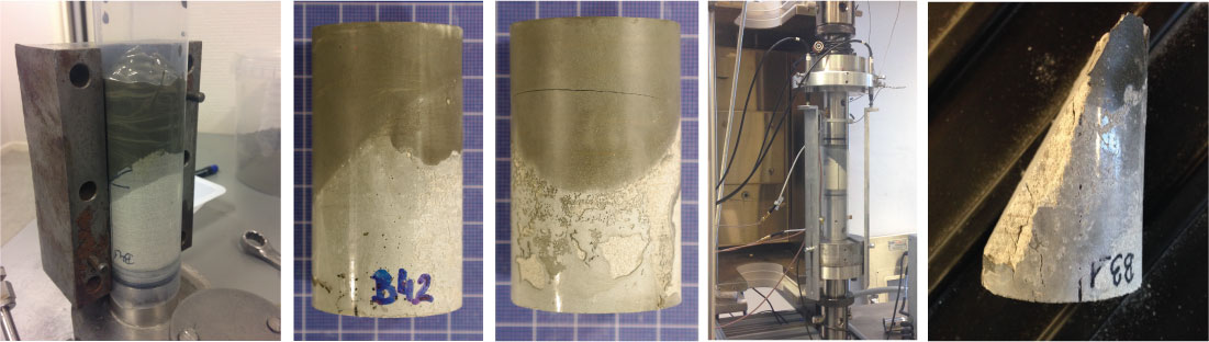
In order to rapidly determine the shear strength of a cement to rock bond, together with exposure effects to drilling mud or (recently) CO2, a “reverse” pushout test has been developed. The original pushout test consists of filling a hollow rock plug with cement, letting it harden, and then literally pushing the cement out while measuring the required force for this. However, especially for brittle rocks, pushing out cement that tends to be stiffer than the surrounding rock often causes the rock to fracture, which produces an incorrect value for the bond strength. This bond strength is an important value to obtain, as it is a much-needed parameter for numerical simulations that are carried out to plan well construction or abandonment, where cement has to be poured to either form a sheath for holding the tubing in place or provide zonal isolation.
Therefore, the reverse pushout was designed to avoid breaking the rock by surrounding a rock plug with cement cast in a mould. The pushout test then consists of pushing on the rock instead of the cement. Results have shown that bond strength is greatly reduced if the drilling fluid or mudcake (fluid filtered by a porous rock such that the particles in the mud are compressed together to form a “cake”) are not thoroughly washed away prior to the cement hardening. Another innovation has been to use µCT scanning technology to provide an image of the interface being studied prior to testing. These images are then analysed to reveal voids, and quantify the total surface where cement is in contact with the rock.
A similar pushout test was perfected to test cement bonding inside a steel casing. Here, the cement plug is cured inside a steel container, which is itself contained in a larger, supporting steel tube, into which a deformation gauge is inserted to contact the lower face of the cement plug. On the top face, a steel piston is in contact with the cement, and the whole assembly is inserted into a load frame, pushing the piston against the top face of the plug. Another deformation gauge is connected to the top piston. The two gauges therefore give an indication of the delay in time for when the top and bottom surfaces of the cement plug start deforming during the test. This allows different cement formulations to be tested and ranked with respect to ductility and deformation prior to the loss of bonding to the steel.
Direct measurement of bond shear strength
Another innovation has been to mimic the field conditions in terms of pressure, stress and temperature as accurately as possible, while still ensuring that the test is relatively easy to carry out and interpret. Composite plugs were created by sawing cylindrical sandstone plugs obliquely and replacing the top part with cement paste in a mould. Hardening was performed at stress conditions that represented operation at 1-km depth, which is typical for CO2 sequestration. This stress corresponds to the weight of a column of cement, and displacing fluid from surface down to the area to be cemented. In addition, pore fluid pressure in the sandstone was applied at a realistic value. This pore fluid action can be considered as equivalent to water permeating a sponge: since water is less compressible than the elastic sponge solid mesh, squeezing the sponge makes water spurt out of it. Similarly, increasing stress in a porous rock (e.g. due to its burial depth) results in either the pore fluid escaping if it can or pressure increasing, as it cannot accommodate so readily decreasing pore space. Taken to the extreme, this can cause the cement between the rock’s grains to crack, which is exactly what happens in hydraulic fracturing operations. Below this fracturing limit, stress on the solid grains decreases somewhat. This means that the cement will probably bond less tightly to the rock framework, but will have access to hydration, which is necessary for it to cure properly.
Therefore, it is believed that taking care to tune both solid stress and pore fluid pressure in the developed experimental setup leads to ensuring the correct and potentially very different bonding conditions rather than letting the cement cure on the sandstone substrate at low pressure and on a dry sandstone specimen. The slanted interface was prepared so that it encouraged slipping along it as a main failure mode, provided that the interface is indeed weaker than either bulk strength in the cement part or the sandstone part of the composite plug. Results showed that the interface was surprisingly strong, and many times as strong or stronger than the rock or cement shear strength (as evidenced by fracturing not occurring at the interface). This reassuring result however did not take into account the poor placement of cement as in the pushout tests described above, wherein mud contamination was introduced.
Direct measurement of bond tensile strength
Since bulk tensile strength is usually about one tenth the value of compressive shear strength in the most porous geomaterials, such as caprock shale, reservoir sandstone and cement, the tensile bond strength of cement to rock should also be much weaker than shear bond strength. Direct measurement of tensile strength in rocks is difficult to perform in the same manner as in metals: a metal specimen is prepared in the shape of an hourglass so that it can easily be pulled axially by gripping the larger end parts, which generates concentrated tensile stress in the middle, thin “waist” part. This does not work for softer, porous rocks, as machining this type of shape readily induces fractures in the sample. However, with careful handling to ascertain perfect axial alignment, geomaterials can be tested in a similar manner, wherein cylindrical specimens are glued with epoxy to metal cups. The upper metal cup is then connected to a chain, itself secured to a load frame piston, while the lower cup is linked with a similar chain to the lower platen. The test thus consists of pulling apart the cups; if the epoxy is stronger than the rock itself, a tensile failure will develop in the rock sample.
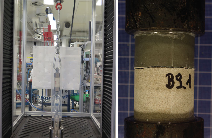
At SINTEF, we have developed this method further to test tensile strength of cement bond to rock, by simply replacing the plugs with composite cement/rock plugs, where the interface between the two materials is perpendicular to the plug’s axis. Again, the cement part on the rock was hardened at controlled applied stresses and with fluid pore pressure in the rock simulating in-situ conditions. Results showed marked differences between sandstone (reservoir rock) and shale (caprock) formations, wherein although the bonding strength was low, even for sandstone, it was almost 0 for shale. This result is interesting, as zonal isolation requirements are mostly relevant for shale sections, where fluid communication between two layers at different depths is only possible at the well. This is due to the almost impermeable properties of shale formations, explaining their preponderance as geological caps for reservoir fluids.
Exposure to CO2
The most recent test campaign run under Task 10 in NCCS has targeted the evaluation of cement plug exposure to CO2, focusing on the effect on bond strength. Several batches were prepared, containing 6-9 samples. Each batch was divided into three groups: the first group (2-3 samples) was used as a reference, with a pushout test producing the shear bond strength as detailed above. The second group (2-3 samples) was exposed to 3.5 wt% NaCl brine and CO2 gas at room temperature. The pressure of CO2 gas was set to around 20 bars. The samples were exposed to this condition for 14 days. After 14 days of exposure, the samples were taken out and a pushout test was immediately performed. The third group (2-3 samples) was exposed to 3.5 wt% NaCl brine and Supercritical CO2 for 14 days. The temperature was set to 42 °C and the pressure was set to around 84 bars. After 14 days, the samples were removed from exposure and a pushout test performed. Two types of caprock shale outcrop analogues were used in the study, Mancos and Pierre I shale.
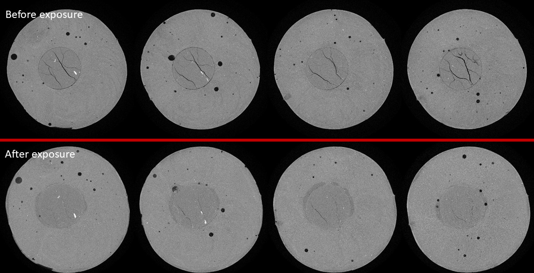
The Pierre I shale specimens which were exposed to brine-CO2 for 14 days at 20 bars at room temperature saw their overall bond strength increase compared to the reference samples. The specimens exposed to brine-CO2 for 14 days at 85 bars and 42°C exhibited a decrease in the shear bond strength. For the Mancos shale, the reference samples exhibited a slightly higher shear bond strength compared to Pierre I shale. This could be explained by the minor lithological difference between these two shale types. The Mancos shale also appears to be less influenced by the exposure conditions than Pierre I shale specimens. The shear bond strength increased somewhat after exposure for 14 days at 20 bars and room temperature.
Conclusion
Wells are human-made constructs that potentially disturb the equilibrium conditions in the subsurface. While the very presence of hydrocarbons attests to the efficient sealing ability of shale overburden, wells penetrate all layers from the surface and down, making for a high-capacity conduit for fluid flow between these layers. The weakest element in the whole system have been identified as the cement bond tensile strength, with steel or shale caprock. Therefore, concentrating efforts on correctly measuring this parameter, in the presence of the fluids intended to stay sequestered in the underground, makes the most sense in helping design better well barrier materials.
I have a real concern about the blooming use of polyamines in the drilling fluids, a highly hydrophobic drilling fluids additive, that so far no provider (mud companies) are able to wash from steel or formations.
From the Cementing companies ? Just a usual Water Base Mud.
The chemist I am can hardly imagine a good bond on an highly hydrophobic film.
Yes, as far as I know, spacer fluids (brines) are mostly designed wrt viscosity and density contrast to ensure stable displacement of mud. Adverse wetting properties would, as you point out, still leave a film on the surface of steel or rock, which has been shown to severely compromise bonding, at least at low pressure conditions.
Pierre