
A new paper from the ACT ELEGANCY project describes the development of a new computer model designed to replicate fluid dynamics in a well and the near-well reservoir. The results will help CO2 storage engineers better understand the temperature and pressure changes and their impact.
Inside a CO2-injection well
The crux of a CO2 capture, transport and storage (CCS) system is to inject the CO2 safely through a well into a permanent underground storage – to keep the CO2 out of the atmosphere. In order to provide guidance in the design and operation of CO2-injection systems, we have developed a computer model describing the fluid dynamics in the well. To do so, we also need to describe the flow in the near-well reservoir.
CO2-injection wells are fed via a pipeline system, or, for offshore reservoirs, also from ships. Although most of the time the CO2 will flow steadily down the well, we must be prepared for changes (transients) as ships come and go, as capture plants increase or decrease their output according to the CO2-capturing process they are coupled with, or during shut-in periods due to maintenance.
This sounds easy enough, but there are several questions that engineers need answers for. How large will the pressure and temperature changes be, both topside and down in the well? Will the valves freeze? Could the temperature cycles be detrimental to well materials? (See blog and article). Will we have one phase, two phases (gas and liquid) or even three phases (gas and two liquids)?
A new computer model that talks to another
To answer some of these questions, Morten Hammer, Åsmund Ervik, Lars Odsæter, Halvor Lund and me have written down the equations describing the flow of CO2 together with other components such as water, and we have implemented a computer program to solve the equations. We also consider the heat transfer from the rock to the well. It turns out that it is not enough to look at the well, we also need to take into account how the fluid flows through the porous rock near the well.
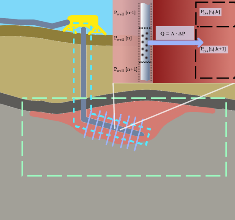
So, we made another computer program describing that as well. The two programs ‘talk’ together so that the conditions in the well and in the reservoir influence each other, and what flows out of the well flows into the reservoir, see the illustration below. This communication, of course, requires some electronic bookkeeping, but performing the calculations in two domains (well and reservoir) has the advantage that it allows us to use methods that are specially adapted for each.
The results of our initial study have recently been published in Greenhouse Gases: Science and Technology. In the article, we show how different reservoir properties influence what happens in the well. We also show how pressure and mass-flow rate vary as might be the case for batch-wise injection from a ship. A final consideration is that of dry-out. That is, brine (salty water) in the reservoir is dried out by the CO2, which can dissolve some water.
In this way, the salt in the brine remains in the pores, which become clogged, hampering the injection. Our results indicate that injecting a small amount of water with CO2 might remediate this challenge.
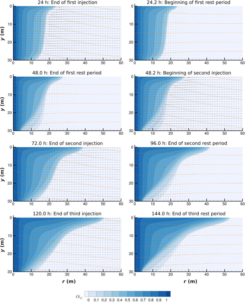
The below figure shows an example of how the CO2 front propagates and partially recedes as a result of batch-wise injection.
In these times with good news for CCS, we are ready to apply the model in current or future deployment cases.
This work was performed in the ACT ELEGANCY project, co-funded by Gassnova in Norway, DETEC in Switzerland, BMWi in Germany, RVO in the Netherlands, BEIS in the UK, industry and the European Commission.
Nice article Svend – are you using Ledaflow for your flow calculations etc ? We’re currently looking into the issues of transportation and injection using Hydraflash – it has a CCS module within it populated by Heriot Watt Carbon Capture teams working with out technical partner Hydrafact (Prof Bahman Tohidi) as we are assessing the potential for hydrates. We’re also using the Hydrasens unit to detect early formation of the hydrate cages. You can see our case studies and an animation on our web site http://www.blue-gentoo.com
Keep up the good work. Stay safe.
Regards
phil
Hi Phil,
In our study, we used a bespoke code – the details are in the article.
Regards,
Svend