Authors from NCCS: Pierre Cerasi, Jelena Todorovic, Martin Raphaug and Alv-Arne Grimstad.
CO2 sequestration in the subsurface should be undertaken immediately and at large injection rates if we are to fulfil the ambitions stated in the Paris Agreement, limiting global average temperature rise to below 2°C. Ongoing research in the Norwegian CCS Research Centre (NCCS) continues to reveal new knowledge that will improve the efficiency of CO2 storage in the decades to come.
One recent learning helps to resolve an instability issue with salt precipitation at specific flow rates. The outcomes should help operating companies adjust their flow rates to save costly salt-related maintenance work later.
Studying salt deposits to save time and money
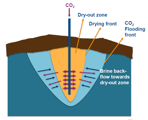
When CO2 is injected into sandstone reservoirs, a drying effect is produced, leading to deposition of salt from the brine present in the sandstone pore network. This crystalline salt can then lead to reduction in the pore volume, strangling the available space for more CO2 to flow through.
Learn more about CCS
Join our newsletter to stay updated with all the latest research results and news from NCCS: The Norwegian CCS Research Centre.
When studying this phenomenon in SINTEF’s Reservoir Technology laboratory, we discovered unusual spiral patterns created by the salt deposits in the brine-bearing sandstone core which was flooded with dry CO2. This pattern appears only for a specific flooding rate, and seems not to be a random occurrence as it was reproduced in a repeat experiment at the same conditions, while not seen at increased flow rate.
Should this be achievable also at the large scale of a real injection well, then it could have implications on CO2 injection operations, removing the need or at least the frequency for clean-up of salt deposits. This would save time and reduce costs, decreasing also the need for using chemical wash of the well and near-well reservoir formation.
Maximising CO2 storage capacity
In the push for decarbonising industry, one very important measure which can yield immediate results is the deployment at unprecedented scale of CCS, CO2 capture and storage. Norway is leading the world in CCS and has been sequestering megatons of CO2 for over 25 years in offshore aquifers, large stretches of highly porous sandstone deep below the seabed. This has shown the feasibility of this technology and proper scaling up could result in gigatons of CO2 being removed from the atmosphere.
To maximise stored capacity, the CO2 is compressed and mildly heated so as to make it transition into the supercritical state. This interesting phase is characterised by a high density but low viscosity; the liquid-like high density means that larger amounts of CO2 can occupy a given space, compared to the gaseous phase, while the lower viscosity, closer to a gas, means that it can flow into its intended storage volume with less needed driving pressure.
CO2 is injected as a dry fluid, meaning that water dissolved in the CO2 is kept at a minimum; this is due to the need to avoid corrosion of steel pipelines and well tubing.
Limitations on injection rate
The injection rate is limited by the available pressure in the well from CO2 compression at surface; the well pressure has to be higher than the pressure inside the pore space of the receiving reservoir, for initiating net flow into the reservoir.
However, another limitation is the stress state in the reservoir: stress is defined as a directional pressure exerted on solid components (rock solid grains in the case of a porous sandstone). The vertical stress component is just the weight of the rock formations from the surface down to the injection point. As in bridge arches, the solid framework of these formations also results in some weight being transferred to the horizontal direction.
Hence the stress state at depth also has two components in the horizontal direction, with one of them almost always the smallest of the 3 components. Therefore, this horizontal stress component sets another limit on CO2 injection pressure, since above its value, fractures will appear in the solid framework of the rock, leading to potential unwanted loss of containment of the CO2 in its designated volume.
The impact on injecting dry CO2
Coming back to our injection of dry, supercritical CO2: this has as one unfortunate consequence the drying of the rock pores in which it is injected. Since these pores were filled with brine (in the case of an aquifer, brine and possibly oil or gas remains for an old hydrocarbon reservoir), the drying is accompanied by precipitation of salt crystals. This phenomenon is analogous to the salt one gets covered with on the skin when drying in the sun on the beach after a bath in the sea.
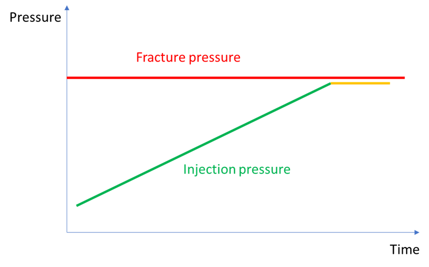
The same drying is used commercially to produce table salt in large, flat basins where brine is left to evaporate in the sun. However, when this occurs in tight pores inside a sandstone, it can rapidly block the available volume for further flow of CO2, or at least gradually restrict this flow capacity. For an operator of an injection well, trying to maintain target injection rates, this will translate in gradually increasing needed pressure at the well head to maintain injection. If this increasing pressure trend is not stopped, the operator risks going over the maximum sustainable pressure and cross the fracture initiation pressure, i.e. exceed the minimum horizontal stress discussed above. This almost happened at the Snøhvit CO2 injection site (although the reasons for the increasing pressure were probably more involved).
Remediation of pore clogging due to salt precipitation requires washing out or dissolving the salt deposits, either with fresh water, and if this is not efficient enough, by adding chemicals to the injected water, such as monoethylene glycol (used at Snøhvit). This means that the CO2 injection has to be temporarily stopped.
However, if the fracture pressure has accidentally been exceeded, or if salt precipitation becomes a recurrent problem, a new injection interval or a new well have to be constructed. Therefore, there would be great advantages in avoiding the situation of precipitation from the outset, or more precisely, fine-tuning the injection rate such as acceptable precipitation occurs, not growing into a flow-blocking pore plug.
A solution found within NCCS
Such a solution had accidentally been discovered in laboratory experiments conducted at SINTEF’s Reservoir Technology laboratory, in the framework of NCCS Task 10, looking at near-well effects affecting reservoir containment risk.
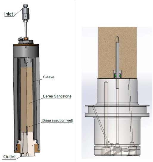
Salt precipitation experiments were conducted in a novel core flooding cell, implementing independently controlled simultaneous flow of dry supercritical CO2 and brine. A core flooding cell is designed such that fluids can be pushed through a porous rock, without choosing the “easier” path around the plug. This is achieved by inserting the plug into a rubber sleeve and pressurising this sleeve at a higher pressure than the fluid entry pressure, thus making for a tight and impermeable sidewall.
The modified design used for the precipitation experiments consisted of inserting a small tube on the bottom surface of the plug (held vertically). Brine was then injected through this opening, while dry CO2 was pumped in the opposite direction, from the top surface.
The reason for this modification was to ensure a brine backflow in the plug; had the brine solely been injected from the bottom surface, chances are that it would not penetrate far enough in the plug to have time and space to mix with the CO2 and expose enough pore room for precipitation of salt. Note that the rock plug was fully saturated with brine to begin with.
By independently tuning the CO2 and brine injection rates, the experiment mimics different well injection rates and accompanying brine capillary backflow in the reservoir pore structure. This backflow occurs due to the rock’s grain surface wetting properties: which fluid preferentially “adheres” to or is repelled from the surface.
If for example quartz grains are preferentially water-wet, drying their surface will induce water from further away to “colonise” the exposed surface the more so if the drying fluid is not particularly compatible with this surface. If the dry fliud is injected too fast, the drying front will propagate too quickly for this backflow to happen. Thus, by playing with the relative injection rates in the experiments between dry CO2 and brine, one can vary the amount of drying and of salt precipitation, as salt amounts increase with brine inflow but salt solubility increases also with increased backflow.
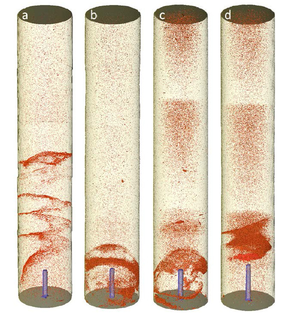
The experiments showed two remarkably different salt precipitation patterns: in one case, a kind of salt dome was created, blocking the whole cross section of the plug. In the second case, a helical precipitation pattern could be observed. This second precipitation pattern was not expected, and a repeat experiment had to be performed, confirming the same pattern, but with lower extension towards the upstream regions of the plug. This is why it is thought that this flow regime is unstable, meaning that the extent of the salt precipitation zone will vary from test to test, although all test parameters are kept the same.
The reasons for this instability are not currently known, but could be related to the occurrence of an unstable front between dry zone and the brine areas, leading to a wave pattern and consequently non-uniform salt precipitation. This flow-related instability is well-known in other cases where one fluid displaces another, for example the fingering instability.
Learn more about CCS
Join our newsletter to stay updated with all the latest research results and news from NCCS: The Norwegian CCS Research Centre.
Much salt precipitation occurred right above the injection point of brine, leading to comparable loss of permeability for the stable dome-type precipitation and helical precipitation. It is however not unreasonable to speculate that in the field, with more extended area for brine backflow, there should be a clear difference between the stable “dome” precipitation and the unstable helix precipitation, in terms of flow impairment.
Thus, it may become a guideline on how to plan injection strategy for optimal CO2 injection with minimal stops and remediation operations, letting some salt precipitate but relying on other “open routes” in the reservoir serving as deviation paths.
Pingback: Eksperimen Pengendapan Garam untuk Peningkatan Penyimpanan CO2 - MAGINFO