
Hydrogen is a clean and sustainable energy vector with applications ranging from small-scale power production to large-scale energy storage. Energy conversion applications include combustion as well as electrochemical energy conversion. These applications have different requirements for purity, and especially fuel cells have strict quality requirements e.g. 99.97 % fuel index. Whereas hydrogen fuel can be produced at the required purity level, the purity level affects the cost of the fuel produced. For hydrogen applications, fuel quality is important for performance and durability of energy conversion systems.
Hydrogen fuel quality is regulated by the standards ISO 14687 and EN 17124, and is classified into grades for various applications. Many applications use catalyst sensitive to impurities like sulfur and chlorine which can inflict irreversible damage.
Comparison of sampling strategies
Sampling for fuel quality control requires representative sampling of hydrogen from the refuelling station dispensing nozzle. The sampling procedure is currently being standardized through the development of ISO/WD 19880-9. This work is led by SINTEF and NPL. Important for the standardization is that current sampling strategies are compliant, and representative of the fuel dispensed.
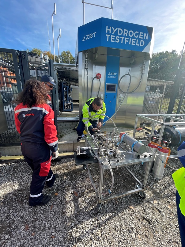
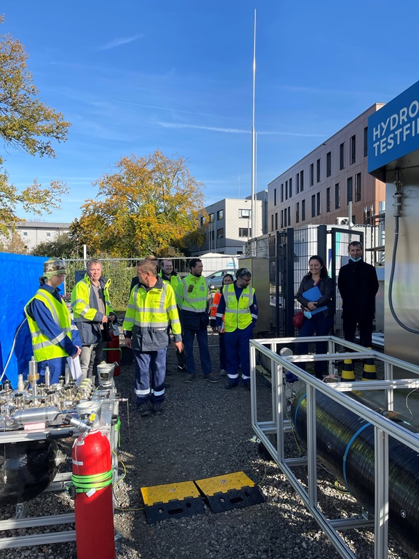
As part of the project Metrology for Hydrogen Vehicles 2 (MetroHyVe 2) a direct comparison of the four known sampling strategies used in Europe was performed at Zentrum für BrennstoffzellenTechnik ZBT GmbH on October 19. 2022. The event took place at ZBT’s test field in Duisburg, where project partners ZBT, ENGIE, Air Liquide, as well as NPL, took samples.
NPL will analyze all samples collected to find out if there are systematic differences between the sampling methods applied given the fact that different sampling conditions and sampling cylinders have been applied.
Sampling strategy 1: Parallel sampling
A parallel sampling approach designates a strategy where a t-piece is used to split the dispensed hydrogen between a sink and a sample container. A normal refuelling is performed according to protocol (SAE J2601), and either a Fuel Cell Electric Vehicle (FCEV) or a simulated tank is used as sink. By using a needle valve or calibrated orifice, the flow in the by-stream can be regulated so the sample bottle is filled whilst covering as much as possible of the refuelling protocol. Pressure regulation is applied to match the desired pressure for the sample container.
Sampling strategy 2: Qualitizer
The Linde Qualitizer sampling was performed by applying a normal fueling protocol, but pre-cooling was set to T20 (i.e. -20 °C). An 244 L Hexagon 70 MPA Type IV tank was used as sink. NPL used a 10 L aluminium spectra-seal lined cylinder with stainless steel valve prepared with a vacuum better than 10-7 mbar.
A small-bore high-pressure hose connects the tee to a 1034 bar Tescom reduction valve equipped with a safety relief valve and a manometer. The flow is throttled to fill the sample cylinder to around 10 MPa in the time it takes refuel a light duty vehicle. The system can be purged through a bleed valve on the Tescom: refuelling is aborted and the Qualitizer depressurized prior to sampling.
Sampling strategy 3: Hy-SAM
The Hy-SAM adapter designed by ZBT and ZSW [1] also offers the option of parallel sampling to up to three sample cylinders of size 2.25 or 10 L; change of sampling time is possible through a needle valve adjusting the flow of sample to the cylinder(s). The system is completely passivated to prevent adsorption of impurities onto surfaces. The system is purged on the high-pressure side by an aborted refuelling. With the sample cylinders pre-filled to 10 bar with ultra-high purity (UHP) hydrogen, purging of the low pressure side of the sampler can also be performed. For this campaign, two 10 L aluminium spectra-seal lined cylinder with stainless steel valve were used. A 244 L tank was again used as sink.
Sampling strategy 4: Serial sampling
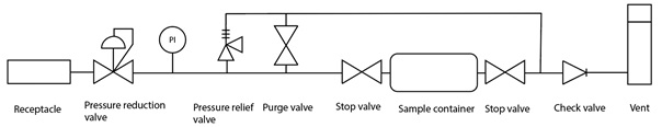
A serial sampling strategy is characterized by performing sampling with a sampling cylinder inline. Since pressure reduction is required, normal refueling protocol operation is not applicable and the Hydrogen Refuelling station (HRS) must be manually controlled for sampling. This prevents a FCEV from being used as sink; either a simulated tank or a vent stack can be used. Purging is normally performed through the line before a sample is collected by closing of the downstream and then upstream stop valves of the sample cylinder.
Air Liquide sampling device
The Air Liquide sampling device is a serial sampling device where sampling if performed to a 5 L aluminium cylinder (no specific treatment) with double-ended stainless-steel valves. The sample cylinder is prepared according to an Air Liquide procedure in order to ensure that it’s not polluted and that the analysis is representative of customer’s product. The cylinder contains a slight overpressure of pure hydrogen at the start of sampling. The HRS was set to provide 180 bar constant pressure and pre-cooled hydrogen to T20. The system was repeatedly (10x) purged by hydrogen from the HRS through pressurization and venting before the procedure was repeated with purging through the sample cylinder (10x). The sample cylinder was then filled to 150 bar. The sampling device has a valve port with pressure reduction for installation of an inline water analyzer. The indication of water content was used to ensure that the water content in the sampler was in line with customer specifications before the sample cylinder was filled.

ENGIE sampling device
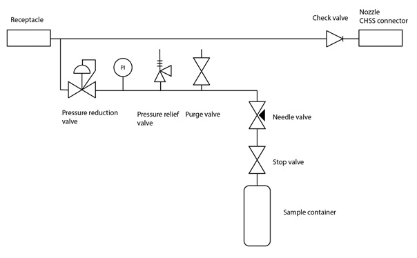
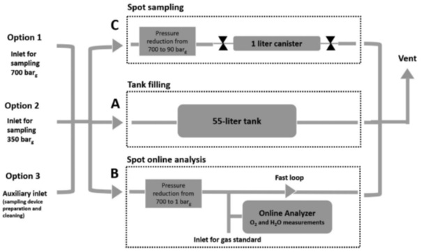
The Engie sampling device is a multi-purpose sampling device for 70 MPa, 35 MPa as well as functionality for online fuel quality control. A schematic is shown in Figure 5. Line C is a conventional sample line where serial sampling with 1 L doble ended cylinders can be performed. Line A incorporates a 55 L composite tank as to allow for simulation of a FCEV. Line B incorporates a fast loop for online analysis. At ZBT, a AP2E Optical Feedback Cavity Enhanced Absorption Spectrometer (OFCEAS) was installed to monitor water, methane, H2S, oxygen and CO2.
The sampling device was connected to the HRS through the 70 MPa receptacle. The HRS was set to provide hydrogen at constant 20 MPa pressure with a T20 pre-cooling. The sampling device was flushed repeatedly (10 times) with nitrogen and UHP hydrogen. Two 1 liter sample cylinders (stainless steel, sulfinert coating) were purged with nitrogen and prefilled with 1 bar UHP hydrogen before installation on the sampling device. The sampling device were purged with nitrogen after use.
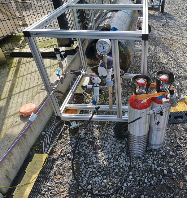
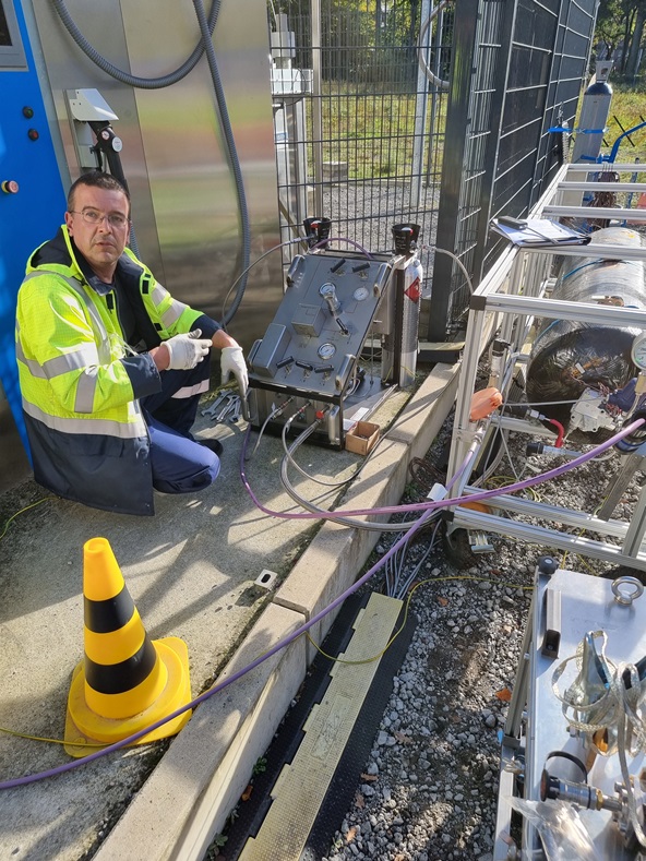
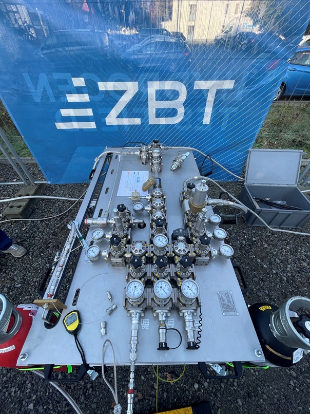
The ENGIE device collected two samples first, and then two samples last of all sampling in order to check of consistency of sampling but also for possible variation in hydrogen quality over time. The installation of the ENGIE sampling at ZBT is shown in Figure 7.
All sample cylinders will be sent to NPL for analysis compliant with ISO 14687. Assuming a constant quality of the hydrogen dispensed from the HRS on the actual day, the difference in analytical results from the different analytical methods will be evaluated. Important for standardization work in ISO TC197 WG33 is to show that the sampling strategies used in Europe produce equivalent results. The results from the online quality analysers will also be evaluated. The results will be published as part of Deliverable 3.2.2 of the MetroHyVe 2. project.
About MetroHyVe 2
The project “Metrology for Hydrogen Vehicles 2” (MetroHyVe 2) has received funding from the EMPIR programme co-financed by the Participating States and from the European Union’s Horizon 2020 research and innovation programme under Grant agreement No [19ENG04].


Comments
Hello,
I would like to inquire whether there is a general methodology, for example in Germany, that establishes a system for hydrogen quality control in relation to its production, storage, transport, and distribution. Specifically, I am interested in aspects such as the frequency of inspections and the key points within the hydrogen supply chain where these controls take place.
Thank you in advance for your time and assistance.
Best regards,
Adéla
Hei,
We have established ISO 19880-9 for sampling of hydrogen fuel from HRS nozzle. For production, storage, transport standard methodologies are not yet established. Regarding frequency of inspection we are currently working on establishing occurrence class data for impurities in hydrogen fuel (ISO 19880-8) that will support decision making. It is expected that national implementation of standards will be different. As an example, in California, the quality at HRS is checked bi-annualy and reported in the NREL quality database.
Hi,
thank you very much for your response. I would like to inquire when you plan to complete the determination of contamination occurrence classes according to ISO 19880-8? In the meantime, would it be sufficient to proceed with creating the hydrogen quality assurance plan based on an actual process evaluation, using technical knowledge of the specific production, transportation, and dispensing processes (as outlined, for example, in the EN 17124 standard)?
Thank you in advance for your response.
Best regards,
Adéla
Hei,
The occurrence classes should be published in the deliverables of https://hyqualityeurope.eu ending in 2025. For now, best approach is to comply with EN 17124. There is a risk assessment approach as well as a prescriptive approach exemplified in that document.
Yours,
Thor
Dear Thor,
Thank you for your responses. I am a researcher from the Czech Republic working at the Transport Research Centre. Currently, I am working on a methodology for evaluating the quality of hydrogen fuel for mobility based on fuel cells. I am unsure whether the Risk Assessment method can be applied at this stage, as there are several pieces of information missing. In addition to defining the contamination occurrence classes based on the number of refuelings, there are also no precise values in the table for determining the impact of impurities on the fuel cells. Such an evaluation could therefore be very inaccurate. Do you know if these values will be further specified? Can this method, in its current form, be practically applied?
Thank you very much for your answers.
Best regards and have a great day.
Adéla