Perfluorocarbon (PFC) gases are extremely potent greenhouse gases (GHGs) and industrial emissions contribute to global warming. In this blog post I will describe what PFCs are and how they are formed, how PFC emissions have significantly lowered over the last 30 years and how continuous online monitoring can help limit and control emissions further.
This may also be of interest:
What are perfluorocarbons (PFCs) and how potent are they as GHGs?
Before we get into how we can monitor PFC emissions I will explain what PFC gases are. PFCs are hydrocarbons where the carbon-hydrogen bonds have been completely replaced by carbon-fluorine bonds. This bond is one of the strongest bonds in organic chemistry, resulting in very stable molecules. This bond strength is utilized in functional materials like Gore-Tex and Teflon.
The atmospheric lifetimes of the gaseous PFCs are very high. For tetrafluoromethane, CF4, it is in the range of 50,000 years. PFCs are also potent greenhouse gases. Their global warming potentials (GWPs) are for CF4 and C2F6 6,630 and 11,100 times that of CO2 in a 100-year perspective!
One of the biggest anthropogenic sources of PFCs is primary aluminium production. Efforts to reduce PFC emissions have been very successful, and the contributions to PFC emission from the semiconductor industry have now become significant.
Emerging is also PFC emissions from the production of rare earth elements like neodymium used in electronic devices.
How are perfluorocarbons (PFCs) formed?
Aluminium metal is produced by converting aluminium oxide, alumina, into the metal form. Alumina is abundant in the earth’s crust and is a more stable form of the element than the metal. Energy is required in order to perform this conversion, and the required energy is provided through the addition of electric current. Alumina is not easily dissolved, but a molten solution of a sodium aluminum fluoride called cryolite at 950 ℃ can be used.
In this way, the current passed through the solution of an electrolytic cell is used to convert alumina into aluminium metal. The oxygen liberated from the alumina reacts with carbon electrodes used to form carbon dioxide, released as gas. During normal process operation, only carbon dioxide is formed, but when the supply of alumina is insufficient, the cryolite will react with carbon to form perfluorocarbons.
Anode Effects (AE) quenching strategies resulting in reduction of PFC gases
Traditionally, PFC formation was associated with discrete events called anode effects (AE), where the electric voltage of the electrolytic cell would increase significantly. In earlier times, the AE was considered a necessity for good circulation of the bath. Eventually, the AEs were not desired because of the release of the perfluorcarbons, but also because they constitute a loss of energy.
Over the past 30 years, there has been a decline in PFC emissions from primary aluminium production, as shown in the figure below.
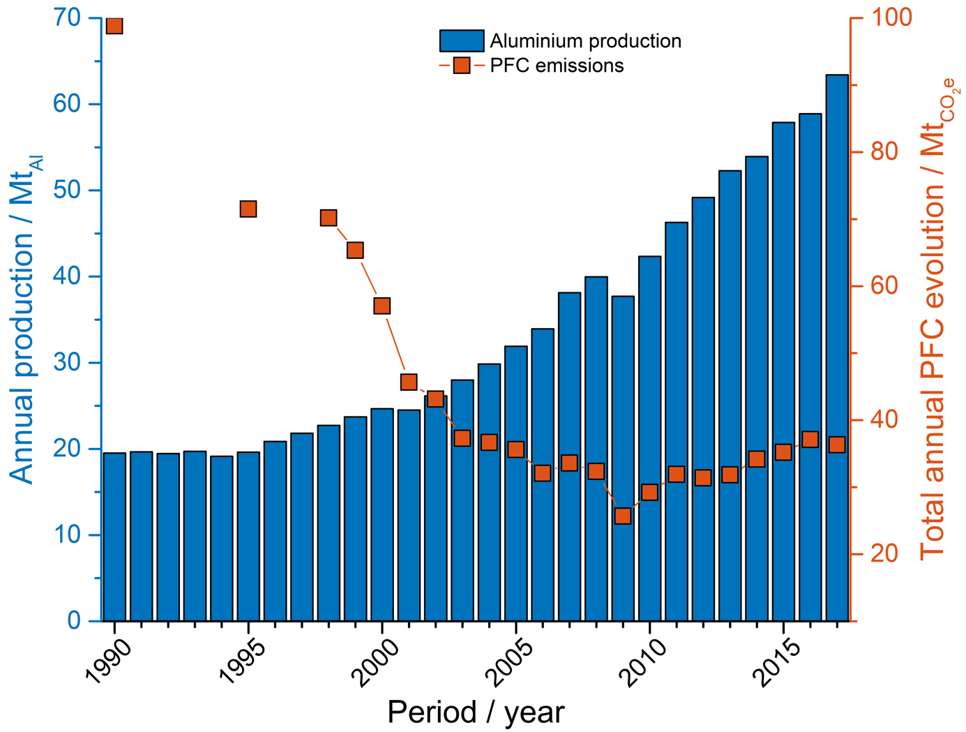
The decline is associated with successful implementation of AE quenching strategies incorporated into the process control of the electrolysis cells. AE quenching strategies have developed from manual insertion of wooden rods underneath the anodes to more complex process control algorithms including pumping and tilting of anodes as well as adjusting the alumina feed rate to the cell.
However, with reduced emissions, and implementation of PFC analyzers with improved sensitivity, came the discovery that not all PFC produced report to AEs [Marks 2012].
Use of online monitoring of CF4 and C2F6 emissions has revealed that low concentrations can still be present in off-gas. Despite the low concentrations, with integration over long time periods, the contribution to the total emissions are significant: estimates as high as 50 % of the total for PFC has been suggested.
Formation of PFC outside AEs are technology specific
High amperage cells contain a larger number of anodes, and the tendency for PFC formation on individual anodes to propagate to all anode and a full AE is lower than for lower amperage cells. This is due to the fact that the current drop on one anode can be distributed to a larger number of anodes. This implies that single anodes can produce PFC for longer periods of time without the occurrence of a full AE.
The PFC produced outside AEs are not easily detected by the process control. The cell voltage is not a good indicator, as all anodes are connected in a parallel circuit. Retrofitting of an individual anode current monitoring system is the ultimate tool to evaluate cell performance. Unfortunately, such systems are too expensive for global implementation in all electrolysis cells. Installation on single cells and in combination with off-gas analysis are the best strategy for understanding and reducing these emissions for the technology applied.
PFC legislation
Up to now, voluntary efforts by the aluminum industry have been the driving force for reduction of PFC emissions. Through organizations like the International Aluminium Institute (IAI) and the Voluntary Aluminum Industrial Partnership (VAIP) program, producers set emission targets and implement a process to monitor and report progress.
The Intergovernmental Panel for Climate Change (IPCC) has published guidelines for good practices for building PFC inventories from production. Their three-tiered approach gives alternatives for reporting emissions:
- Tier one uses technology specific default emission factors to correlate metal produced with PFC emissions
- Tier two establishes a slope factor for emissions based on anode effect performance
- Tier three involves direct measurements of the actual PFC emissions
Tier three provides the best estimates of the actual PFC emissions. It is facilitated by the use of online monitors, either continuously or by conducting audit campaigns.
Environmental legislation is moving towards continuous, online (tier three) monitoring of industrial emissions. The motivation for this is to provide better budgets for the emissions. But online monitoring also provides an opportunity to correlate emissions with the process. In this way, emissions can also be reduced. In the European Union, the best available technology conclusions (BATC) and reference documents (BREF) describes best available technology for reducing PFC emissions. PFCs are expected to enter the EU Emissions Trading System (EU ETS) in the future.
Instrumentation for PFC monitoring and emission estimation
Extractive Fourier transformed infrared spectroscopy (FTIR) has been the best approach towards the estimation of PFC emissions. With multivariate calibration models, interference from methane and water can be minimized, and the sensitivity of the instruments for PFC adjusted with light path length.
The downside of FTIR instruments is the instrument cost and maintenance requirements. Calibration and operation of the instrument requires a highly-trained operator. Not many instruments are applied for continuous emissions monitoring in aluminium smelters today [Aarhaug 2018].
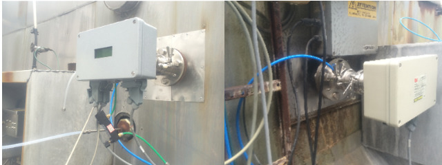
Tunable diode laser instrumentation are low cost and low maintenance instruments, frequently used in aluminum industry to monitor fluorine and dust emissions. Historically, lasers have not been commercially available in the frequency range needed for CF4 monitoring. With emerging quantum cascade lasers, a commercial continuous emissions monitor is now available from NEO Monitors in Norway.
PFC monitoring through the HighEFFLab infrastructure
Through the HighEffLab infrastructure grant, SINTEF has acquired a LaserGas Q CF4 from NEO. SINTEF has tested the instrument calibration in the laboratory. Since the instrument uses a single frequency to quantify CF4, it was important to investigate the impact of relevant impurities like water and methane.
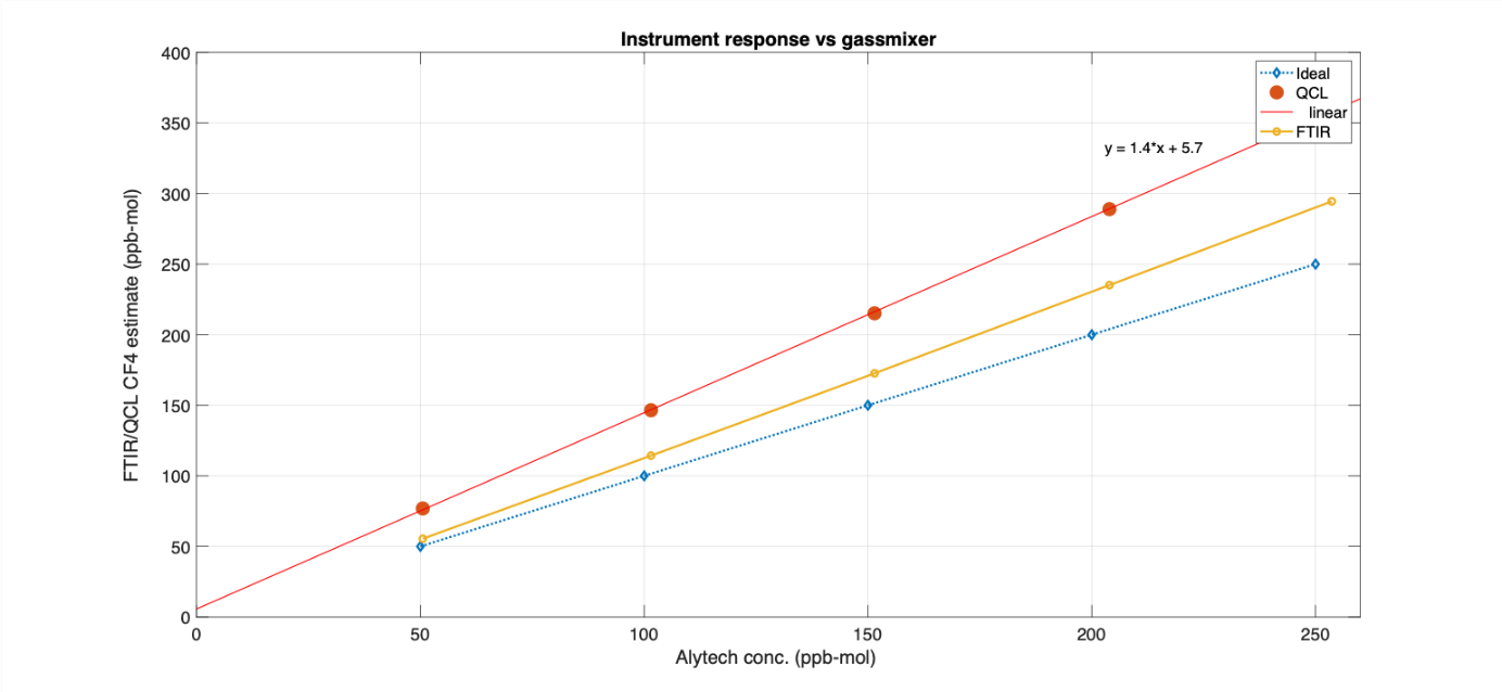
The results from testing indicate that while the interference from water is negligible, there is a significant impact from methane. The interference was quantified to be 3.1 ppb mol per ppm mol methane present.
Online monitoring of PFC in SFI Metals production
SINTEF Industry has through the SFI Metals production RD4 worked with emissions from industry. For PFC, the goal is to provide better estimates of emissions by monitoring on gas treatment center stacks. Online data of the emissions could provide information about not only the absolute emission but also the variance in emissions.
Improving the process control in order to reduce PFC emissions can be performed when combining anode current distribution monitoring with gas monitoring. With the LaserGas Q mounted on the duct of a single cell, the PFC production can be compared to the applied process control and resulting current distributions between anodes. Evaluation of impact on PFC generation from cell operations like anode shift and metal tapping can also be performed.
SINTEF Industry is currently cooperating with Alcoa Norway, and the LaserGas Q is currently installed in their smelter in Mosjøen. The prebake cell technology in Mosjøen represent small cells with 18 anodes. SINTEF Industry is aiming at finding collaborators that will allow for monitoring of cells with a larger (> 40) number of anodes.
Literature
- J. Marks, Sally D. Rand, Implications of non-anode effect-related PFC emissions from primary aluminium, Greenhouse Gas Measurement and Management 2 (4), 2012 pp. 171-177.
- T. Aarhaug, A. Ferber, H. Gaertner, S. Kolås, S.O. Ryman, P. Geiser, Validation of Online Monitoring of PFC by QCL with FTIR Spectroscopy, Light metals 2018, pp. 1487-1493, (https://doi.org/10.1007/978-3-319-72284-9_194)






Comments
This is important work, because there is not a lot of published work that correlates process parameters (e.g. current distribution) with PFC emissions. I am also very eager to monitor on the stack of large GTC’s in order to investigate if the instrument sensitivity is sufficient to monitor the continuous PFC emissions from 100+ cells.
A master student at NTNU is performing experiments and looking at data from a single cell at Alcoa Mosjøen to better understand conditions for creation of PFC outside of anode effects. It is apparent that current distribution and variations in cell voltage (noise) correlates with PFC generation as does the disturbance when old warm anodes are replaced by new cold anodes.
Bueno el comentario. Las perturbaciones durante el cambio de Anodos son indicativas de lo que sostengo durante años. El Anodo caliente está a más de 1200°C. Temperatura que permite la “Dilución” de la Alúmina. Al incorporar uno frío la Alúmina no se diluye. El Flúor formado por la descarga del ion Fluoruro en el Anodo, no encuentra Alúmina diluida con quien reaccionar para que, desplazando el Oxígeno, vuelva a Formar Fluoruro de Aluminio. Entonces reacciona directamente con el Carbón del Anodo, formando PFC, estable. Por eso a las cubas con precocidos se les atravezaba un Palo Verde, cuanto más verde mejor, Se forma Hidrógeno Gaseoso, que no solo remueve por burbujeo… El Flúor lo prefiere para reaccionar, antes que al Carbono. Pero se forma FH. Las Cubas con Anodos crudos emiten menos PFC, … pero más, mucho más Fluoruro de Hidrógeno, que a esa temperatura tambien es estable. Con Anodos precocido emiten menos FH, … pero más PFCs. Y atención: The Science of Air Pharmacology or Chemtrails by Jim Pelps.
Muy buen comentario. De rato reclamo por la Verdad en el proceso H.H. Y esto sobre las causas de producción de PFCs CONSTANTES y no solo durante los E.A., es parte de la Verdad que reclamo.