During the TCCS9 conference in Trondheim, Mari Voldsund from SINTEF Energy Research presented the CEMCAP framework for CO2 capture from cement plants that was recently published on the CEMCAP website. The framework has been developed in CEMCAP with participation from VDZ, SINTEF Energy Research, Politecnico di Milano, ETH Zurich, Italcementi and TNO.
Reducing CO2 emissions from cement production with CCS
CO2 emissions from the cement industry constitute 7-9% of global anthropogenic CO2 emissions, which is a considerable share. Furthermore, in a typical cement plant, 60% of the emissions come from calcination of limestone (CaCO3 -> CaO + CO2), while 40% comes from fuel combustion.
The amount of CO2 generated from combustion could be reduced by fuel substitution, but the CO2 generated in the calcination reaction cannot be avoided. So, if we want to produce cement, we have to generate CO2. Therefore, CO2 capture and storage (CCS) is the only viable technology for significant reduction of CO2 emissions from the cement industry.
Investigating four technologies
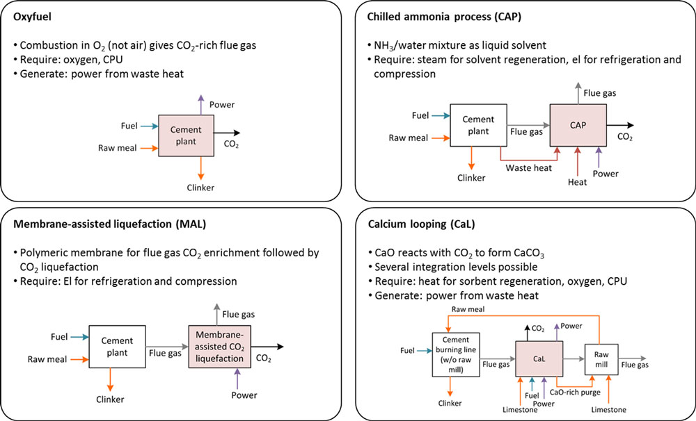
The CEMCAP project investigates four fundamentally different technologies for CO2 capture from cement plants. The technologies are
- Oxyfuel,
- chilled ammonia process (CAP),
- membrane-assisted liquefaction (MAL)
- and Ca-looping (CaL).
The differences in how these processes are integrated in a cement plant, which utilities that are required, and whether there could be associated power generation are shown in the figure below. Four different CEMCAP partners simulate these four capture technologies.
The CEMCAP framework has several important functions within CEMCAP:
- It provides a useful information basis for experimental research and process simulations
- It enables consistent process simulations and comparative assessment of the technologies
- It gives transparency on how the CEMCAP project results are obtained
In addition to this, the CEMCAP framework could also be useful for research outside of CEMCAP. It gives an information basis relevant for CCS researchers that want to focus their attention towards the cement industry.
The framework contains:
- A reference cement burning line
- Process unit specifications
- Utilities – cost and climate impact
- CO2 specifications
- Economic parameters
- Key performance indicatorsThe TCCS9 presentation as well as this blog focus on the reference cement burning line and the utilities.
The reference cement burning line
All cement burning lines are different. They can have different kiln systems, raw materials, fuels, configurations, sizes, etc. As a result, the CO2 concentration in the flue gas of European cement kilns vary in the range of 14-35 vol% (dry basis).
Therefore, a reference cement burning line has been defined in CEMCAP. The reference cement burning line is based on the reference kiln defined by ECRA (European Cement Research Academy). It is a dry kiln process, and BAT (best available technique) technologies are assumed to be used. Simulation of the reference cement kiln is described in CEMCAP deliverable D4.1.
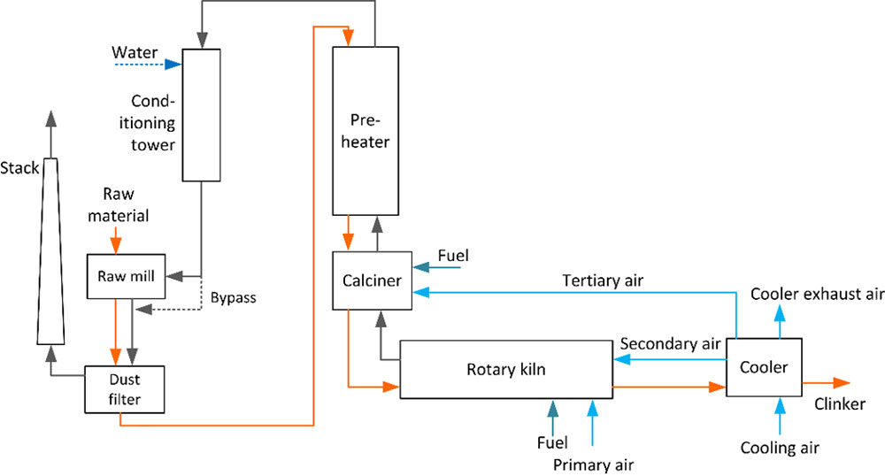
The raw material entering the process is first ground to form raw meal in a raw mill, before it is preheated in a five stage cyclone preheater, and calcined in a calciner with tertiary air duct. After the calciner, the raw meal is sent to the rotary kiln, where it is heated to more than 1450 °C to form clinker. The clinker is cooled in a grate clinker cooler. Flue gas is formed from combustion in the rotary kiln and the calciner and from the calcination of the raw meal, mainly in the calciner. The flue gas is sent to the preheater for preheating of the raw meal, and thereafter to the raw mill for drying of the raw meal. The mix of flue gas and raw meal from the mill is separated in a filter, before the flue gas is sent to the stack.
The raw mill is out of operation a couple of hours every day, and then the flue gas is bypassed the mill (so-called direct operation). In this mode, the flue gas is cooled by spraying water in a conditioning tower, in order to prevent too high temperatures for the filter.
Cement kilns are run slightly below ambient pressure, and therefore air will leak into the process at several points. The amount of air leakage is typically low right after maintenance, and increases until the next maintenance. For the reference cement burning line, two scenarios are defined: low air leak resulting in 25 vol% CO2 (dry basis) at stack, and medium air leak resulting in 20 vol% CO2 (dry basis) at stack.
Different utilities are required
Depending on the technology, different types of utilities are required.
Steam
Some CO2 capture technologies require heat in form of steam. Unlike the case of e.g. coal fired power plants, there is normally no steam available at cement plants. At most cement plants there are also little waste heat available for steam generation as well. One exception is the Norcem cement plant in Brevik, which has very dry raw material, and therefore excess waste heat. At the CEMCAP reference cement burning line it is assumed that a small amount of steam can be generated by waste heat recovery from the cooler exhaust air. The majority of steam required in technologies that implies solvent regeneration is assumed to be generated either by installation of a natural gas fired boiler or to be extracted from a coal fired heat and power plant nearby.
Electricity
All technologies require to some extent electricity. Cost and climate impact of the electricity, and efficiency of the electricity generation, is estimated based on information from Eurostat and IEA. The base case in CEMCAP is the average electricity mix in EU-28. Alternative cases with specific electricity generation options are defined, in order to allow case studies.
Integrated power production
For oxyfuel and calcium looping capture technologies, a significant amount of waste heat is available from the process. Such heat can be recovered by feeding a heat recovery steam cycle. In conventional cement kilns, heat recovery steam cycles are very seldom adopted, due to the small amount of waste heat normally available. However, reference can be made to waste-to-energy plants, and steam cycle parameters for integrated power production in CEMCAP are based on properties of such plants.
Oxygen
Both the oxyfuel and the calcium looping capture technologies require oxygen as input to the process. The CEMCAP framework defines two options for oxygen supply: (i) generation on-site with air separation unit (ASU) or (ii) oxygen delivered by trucks. The first option is cheapest, but it is also the least flexible option.
Refrigeration
Refrigeration is required both in the chilled ammonia and the membrane-assisted liquefaction processes. In order to easily estimate the power requirement of the refrigeration system, a relation between coefficient of performance (COP) and evaporator temperature of the refrigeration system is defined in the framework.
Other information available
The CEMCAP framework also defines process unit specifications, CO2 specifications, economic parameters and key performance indicators. It can be downloaded from the “results” section of the project website, along with other public CEMCAP deliverables.







Comments
No comments yet. Be the first to comment!