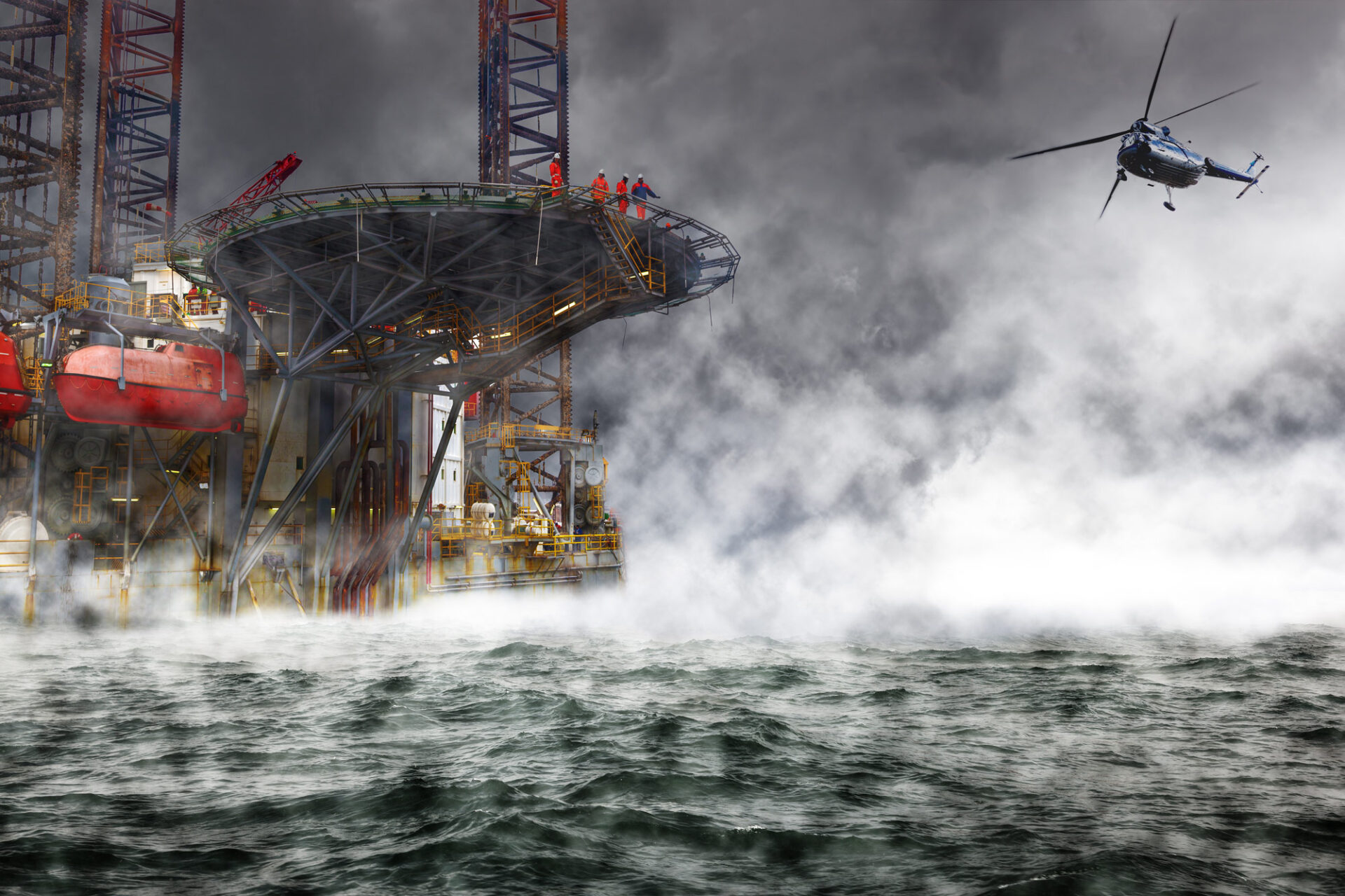

The design of both the helideck and the vessel or platform it is on can be contributing factors. Computational fluid dynamics (CFD) can be of assistance to identify how much turbulence is due to their design, and to evaluate impact of design changes. Pilots describe turbulence as a major contributor to safety hazards. In addition to the weather, the presence and operation of the offshore installation itself causes changes of wind pattern in its surroundings.
What do the regulations say about turbulence on helideck?
The CAP 437 Standards for Offshore Helicopter Landing Areas, which is an accepted world-wide source of reference for helicopter landing on offshore installations, has defined a criterion to evaluate whether those disturbances can lead to hazardous operations. This criterion is based on the fluctuations of the vertical air flow, i.e. the standard deviation of the vertical velocity. As a general rule, it should not exceed 1.75 m/s. Above that value, the pilot should be warned of noticeable turbulence, and operational activity restrictions on the vessel or offshore installation may be necessary. For conditions where this criterion exceeds 2.4 m/s, design modifications are advisable in order to avoid operating restrictions. A good helideck design will ensure that the vertical velocity fluctuations are minimised, and consequently that the operational windows are maximised.
How to evaluate turbulence levels when designing a helideck?
Standards recommend conducting either wind tunnel tests or Computational Fluid Dynamics (CFD) analysis to document the wind velocity, direction and vertical velocity fluctuations on the helideck in different operational conditions.
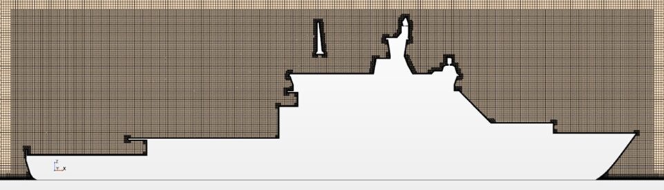
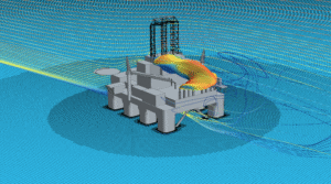
Computational Fluid Dynamics (CFD) has become increasingly popular to assess the wind field properties over the helideck. With this method, a 3D model of the offshore installation is placed in a computational domain which is discretised in several million cells, as shown in Figure 1. An undisturbed atmospheric wind profile is imposed at the boundaries of the domain, and the CFD analysis computes how the wind field is affected by the presence of the offshore structure.
CFD presents several advantages compared to performing model tests in a wind tunnel
- It is performed in full scale, ensuring the correct regime for important non-dimensional numbers describing the flow field, such as the Reynolds number;
- It provides information about the 3D features of the flow, allowing to identify the source of the largest turbulence structures;
- It is flexible in terms of modifications of the design after study of preliminary results;
- It is cost efficient since it does not require manufacturing of one (or multiple) instrumented physical model and all costs connected to running the experimental facility are avoided.
It is however essential to use the right mathematical models in the CFD simulations to obtain results that can be trusted.
How will turbulence modelling in CFD impact my results?
In CFD analysis, turbulence (i.e. velocity fluctuations) is resolved down to a certain size of vortices, while turbulent vortices under that scale are modelled by mathematical models. Different turbulence models based on different assumptions exist, and not all models are suited to all purposes. Choosing the wrong model can lead to incorrect results. Because standards do not specify which modelling approaches are suited to the study of turbulence over helideck, the Marine CFD team at SINTEF Ocean compared two of them on the helideck of a vessel sailing in different wind conditions.
In a first set of simulations, a standard two-equations turbulence models used in Reynolds Average Navier-Stokes (RANS) is used. This model assumes among others that the turbulence is isotropic. In a second set of simulations, an unsteady Detached Eddy Simulations (DES) model is used. With this approach large scales of turbulence are directly solved.
Differences can be observed in the vorticity field obtained with the two models, where vortices of large scales are only captured by the DES model (Figure 2). The corresponding values of mean and standard deviation of the vertical velocity above the helideck are compared in the middle column in the same figure.
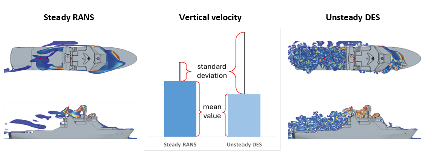
Although the mean values obtained with different models are in fair agreement, the standard deviation computed with the unsteady DES model are much larger than the corresponding value computed with the steady RANS model. This implies that the velocity fluctuations above the helideck are much larger when using the DES model and the RANS model would in this case underpredict velocity fluctuations, possibly compromising a safe helicopter landing.
Despite the increased computational time required by DES compared to RANS model, this comparison shows that scale resolving turbulence models are required to capture the large turbulent scales in the aerodynamic wake of offshore installations and accurately predict the turbulence levels and velocity fluctuations on helidecks.
Those findings are also of importance for helicopter operation in offshore wind farms, where the vortices present in wind turbine wakes can create turbulence levels that will challenge operations.
For more information, contact Senior research scientist Andrea Califano or Research manager Eloïse Croonenborghs.


Comments
No comments yet. Be the first to comment!