
Computational Fluid Dynamics
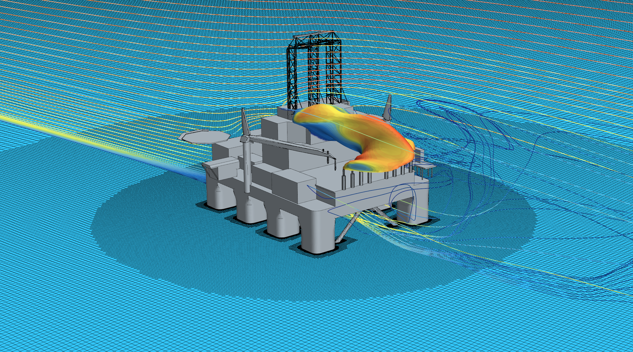
How a released gas spreads out (dilutes) in space over time depends on several physical processes. When a gas is released in air (or another medium), it will spread out (mix), carried by wind or flow (advection), affected by turbulence, buoyancy (if its density is different), obstacles, etc.
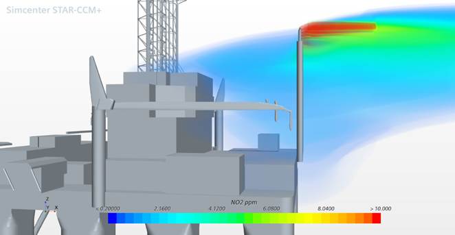
While analytic or semi-empirical plume rise models give useful first approximations, Computational Fluid Dynamics (CFD) is more detailed, resolves the flow field, considers temperature, turbulence, mixing, and it is suitable for complex geometries. For these reasons it allows for a more detailed exploration of how the height of the stack (or release point) and its position, relative to other structures and terrain / sea surface, affect the spreading of pollutants and their concentration in sensitive areas.
Validating the tool
A large CFD study on gas dispersion from an offshore rig was performed by SINTEF, using RANSe methods, where the Navier-Stokes equations, expressing the fundamental principles of fluid mechanics, are solved in a time‐averaged sense. Turbulence effects are modelled rather than resolved in full detail, making RANS generally much cheaper computationally than LES (Large Eddy Simulation), and feasible for many practical engineering cases.
Different cases/scenarios were considered, and alternative stack design solutions analysed. The CFD results for the existing rig were firstly validated against field measurements and observations. The main insight is that stack height and stack position matter and that they can have a strong effect on the dispersion of pollutant from the exhaust gas.
Being upwind gives cleaner flow into stack and less downwash; being downwind can put the stack in a disturbed flow region. The lateral position, the proximity to edges or corners, or being near the leeward side of buildings, can also expose the plume to recirculation and low‐pressure zones.
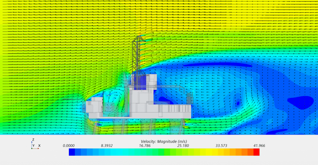
Obstacles generate turbulence and modify flow patterns (accelerating, decelerating, deflecting the flow). The stack release height interacts with those turbulence fields: a lower release height may embed the plume into a complex turbulent area, enhancing mixing (good in some sense) but also increasing ground‐level exposure.
When a stack is placed too low relative to nearby structures or other obstacles, the plume can be caught in the wake or recirculation zones. It is the so-called downwash effect, that causes plume bending downward or spread laterally, near the ground, which leads to higher ground‐level concentrations.
Increasing the stack height above the zone of disturbed flow may avoid some of the turbulence so that the plume rise may be less impeded, but the results may be very sensitive to the height of the release point. Small variations of the pipe’s length can cause the plume tip being ‘pulled’ into the wake of the other obstacles and sucked back toward the recirculation zone (low pressure area). Especially if the exhaust velocity is not much greater than the ambient wind speed.
Taller stacks raise the release point above much of the obstacle‐generated turbulence and avoid trapping the exhaust in wakes. This gives the gas more distance and time to dilute before reaching the ground, reducing the pollutant concentration on the pipe deck.
However, there’s often a trade‑off: raising the stack beyond a point may only marginally reduce ground concentrations, while cost (construction, monitoring, structural, maintenance) rises steeply.
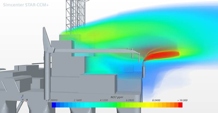
The stacks can be moved away from the wake region not only vertically but also horizontally (e.g. to corners), or one can increase the distance between each single stack. This can have a strong effect on the gas dispersion. Four alternative pipe routings were analysed by CFD, and the optimal design was identified by comparing the level of NO2 on the pipe deck. The optimal design was the one providing the maximum reduction of ground‐level concentrations of pollutant, having them below a certain acceptable threshold.
Performing RANS-CFD
RANS-CFD allows accounting for the buoyancy flux (temperature, density difference, heat content). This is crucial in determining how the plume rises before it reaches the same density as the surrounding air.
In neutral stability, for instance, the surrounding environment does not strongly resist upward motion; but even then, as the plume rises it cools and mixes with the surrounding air, and so eventually reaches a neutral buoyancy height.
The temperature and the exit velocity of the gases define the boundary conditions – they influence the initial momentum factor. If the plume is ejected with high velocity, momentum can carry it upward and outward before buoyancy dominates.
To correctly model the interaction between the plume and the surrounding environment it is crucial to follow some General design and modelling recommendations:
- Use a realistic ABL profile
Use an appropriate profile for wind speed, turbulence kinetic energy, dissipation, and temperature stratification. And set the surface roughness (z₀) at the ground and wall functions correctly. - Use appropriate turbulence model(s):
Some RANS turbulence models perform better under certain stability/roughness conditions. - The domain height must be above stack and mid‑ABL height:
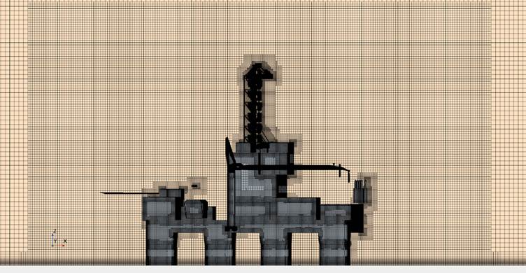
The upper boundary of the modelling domain should be sufficiently above the highest expected plume height or ABL top to avoid artificial reflection/confinement of the plume rise. - The mesh resolution must be tailored to capture surface/obstacle influence and turbulence:
The vertical resolution in the lower part of the ABL (surface layer) is critical. Special care must be taken near the source stack, building edges, obstacles and wall surfaces, to resolve shear layers and wakes. - Simulate multiple stability conditions:
Design for worst conditions, like neutral or stable conditions. Unstable ABLs boost the vertical motion and the spreading out of pollutants. - Model multiple scenarios, wind directions and alignments (upwind/ downwash):
Consider prevailing wind directions and wind speeds and different alignment stacks/obstacles. Even tall stacks may suffer downwash if they are in the lee of tall obstacles when in the ABL’s wind profile or for certain wind conditions. - Validate:
Validate where possible with experiments or field data.
Conclusions
RANS CFD provides a practical and cost‑feasible way to explore how changing height or shifting the stack location alters plume rise, ground‑level concentrations, and exposure risks. While simplified plume models are useful for screening, CFD helps in fine‑tuning designs, especially in complex-built environments like offshore facilities.
When designing or assessing a site by CFD RANS, it is a good practise to perform simulations for a range of stack heights/locations and wind directions to identify “weak points” and “worst scenarios” and ensure compliance across different conditions.


Comments
Hi
I hope you are doing well. it is possible for you to teach me how to model gas dispersion with CFD?