


Greenhouse gas emissions from maritime transport represent around 3% of the of our global emissions. The whole shipping community, under pressure from the authorities and the public, leaves no stone unturned to reducing its footprint, while continuing profitable operations. This leads to a world-wide brainstorming to not only optimize, but also radically change the design of cargo ships. Alternative fuels, new operational schemes, novel ship and appendage designs have been explored, among others. And one dimension that has gained significant momentum during the last couple of years is wind-assisted propulsion.
Wind-assisted propulsion: a challenge for designers and researchers
Wind has been the prime mover of ships for centuries, and the idea of using wind assistance for the propulsion of modern ships dates back to the early 1900s. Wing sails, rotor sails, and even kites have been proposed (see Figure 1), and some of these solutions have been pilot-tested on real ships. But there is still a knowledge gap in the design and operation of wind assisted propulsion, as many aspects of the ship system are affected. Wind forces causes, for example, the vessel to drift sideways, which increases the hull resistance, rudder use, and hence energy consumption. Another important effect is that the ship machinery experiences a different type of loading due to the help of the sails and the change of propeller inflow angles. Modelling each of these effects individually is challenging enough, but modelling the interaction between all effects (hydrodynamic, aerodynamic, machinery, etc…) will keep designers and researchers busy for the years to come.
A new experimental method
SINTEF Ocean has supported the ship design community for decades, by providing high-quality experimental data in the form of towing tank tests at reduced scale (typically 1:10 – 1:35). Such tests enabled to confirm the performance of a design, propose improvements, calibrate numerical models, and sometimes discover unexpected effects. To perform model testing of wind-assisted cargo ships, towing tank tests require the application of wind forces on the model. And here, things get complicated. Indeed, wind-related effects (where viscous effects matter) follow so-called Reynolds scaling, while wave-related effects (where gravity forces matter) are subject to so-called Froude scaling laws. And it is impossible to fulfil Froude and Reynolds number similarity at the same time at small scale. Furthermore, there are technical challenges to generate a wind field of appropriate quality around a moving object in a hydrodynamic laboratory.
We have fortunately several tricks in our bag, and one of them is called cyber-physical testing (or ReaTHM® testing, a trademark of SINTEF Ocean). In such a method, one part of the system is modelled physically, while the other part is modelled numerically. Both physical and numerical “substructures” interact, in real-time, through sensors, actuators, observers, and other algorithms. So here, the wind field and rotor sails are modelled numerically, and interact in real time with the ship that is modelled physically. This enables to have total control on the aerodynamic loads, and focus our experiments on the hydrodynamical aspects.
Pilot study using a bulk carrier, equipped with four rotor sails.
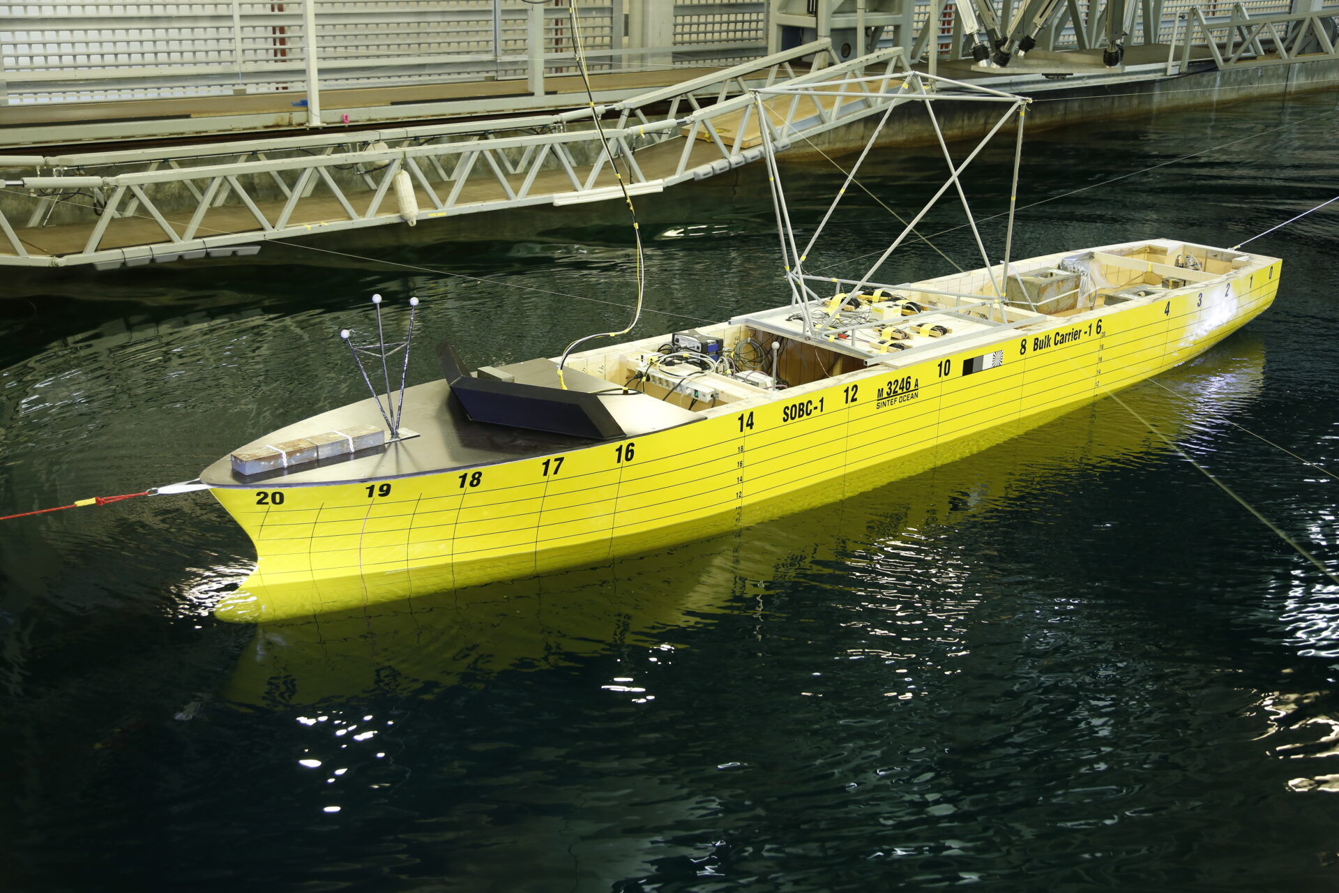
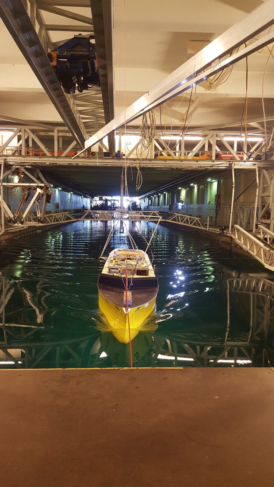
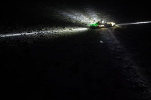
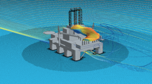
In May 2021, we performed, for the first time, such tests on an in-house bulk carrier design represented in Figure 2. In Figure 3, the ship under (virtual) sails is seen. On this picture, the (virtual) wind was blowing 50 degrees of the bow, what sailors call “close-hauled” sailing.
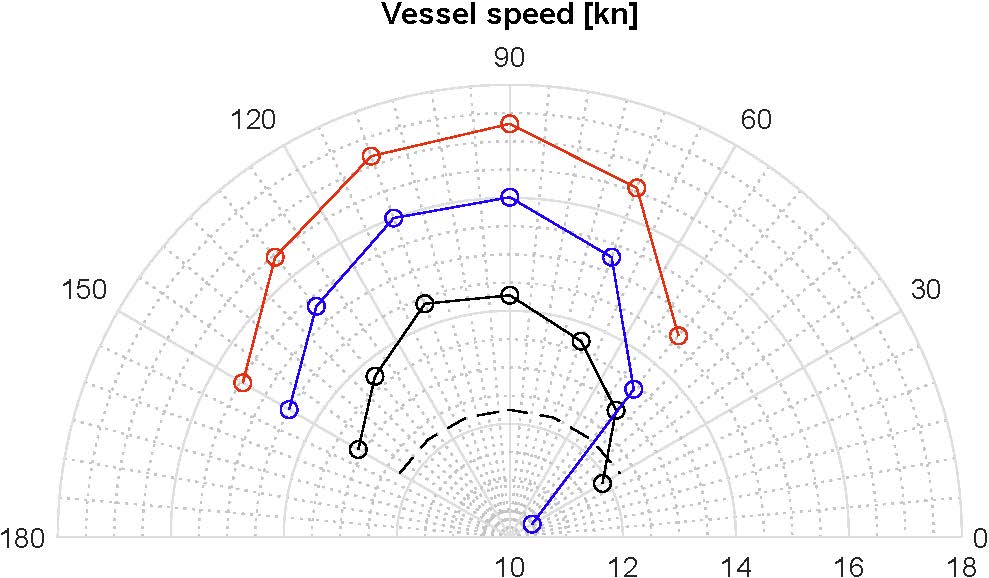
What did we learn from these tests? Figure 4 shows how the speed of the vessel changed with the wind direction and velocity, while the main engine power was kept constant. We see that the vessel speed could increase significantly when using sails, here from 12.25 knots (reference speed without sails) to beyond 17 knots, which was achieved in beam wind (wind from the ship’s side). This also means that, if aiming at keeping a constant speed, the vessel could significantly reduce its engine power, and reduce emissions.
We also observed that, as expected, the sails could cause a significant reduction of speed for some wind angles (when sailing close-hauled). This is of operational importance, as it indicates when sails should be “reefed”, or put down on deck.
A significant advance towards a complete understanding of wind-assisted propulsion
Figure 4 constitutes only a fraction of the results obtained from these tests. We could also study in detail how much the rudder had to be used to keep the course of the ship, how much the ship heeled due to the sail forces, how the propulsion operating point and propeller efficiency changed due the wind-assistance, and so on.
Studying wind-assisted cargo propulsion with this new (cyber-physical) empirical method is the beginning of an exciting journey. We think that this method will constitute an important contribution to understand all involved interaction effects, and we hope that in the long run, we can contribute to radically new ship designs and drastically reduced emissions from the shipping segment.


Comments
Link to the journal article (Open Access):
https://www.sciencedirect.com/science/article/pii/S0029801821015213
@Alvaro del Toro:
http://www.mathisruhl.com/MR%20diaporamas/Wind%20Motion%20120M/index.html
May I ask if the lift coefficient results of different types of sails were measured through wind tunnel tests or CFD simulations.
@Chenze Cao: sure, we have used CFD simulations presented in the following paper: De Marco, A., Mancini, S., Pensa, C., Calise, G., De Luca, F., 2016. Flettner Rotor Concept for Marine Applications: A Systematic Study. International Journal of Rotating Machinery 2016, 1–12. https://doi.org/10.1155/2016/3458750
However, the polynomial coefficients used to describe the lift in that paper lack significant digits, and cannot be used. For the correct values, see Appendix A in our paper:
Sauder, T., Alterskjær, S.A., 2022. Hydrodynamic testing of wind-assisted cargo ships using a cyber–physical method. Ocean Engineering 243, 110206. https://doi.org/10.1016/j.oceaneng.2021.110206
Dear Thomas,
Please, could you give the full reference for “Ruhl 2019”?
Thanks in advance.
Regards,
Alvaro
@Sandip: you’re entirely right. We have performed such cyber-physical experiments since about 2015. It has so far been to test floating wind turbines, but sail-assisted ship is next on the line indeed.
Thanks to both for your positive feedback.
Really nice but complicated initiative…. Bravo?
Kindly elaborate ” one part of the system is modelled physically, while the other part is modelled numerically.”
Here one part is ship model and other part is wind system..? Is it right?
Dear Thomas Sauder
This is a valuable contribution bringing the issue at the correct direction.