

Using interconnected barges as floating yards can facilitate the fabrication, assembly, and deployment of offshore wind turbines. Designing such modular structures require knowledge of their dynamic behaviour in waves, but it can be challenging to model the dynamics of these multi-body systems numerically. This is mainly due to the dynamic couplings resulting from the articulations as well as the hydrodynamic interaction between the floating bodies.
This has prompted an experimental model test campaign to investigate the feasibility of these floating offshore wind yards (FOWYs). The model tests were conducted in the Ocean Basin Laboratory for three configurations of FOWYs at a 1:50 scale, namely:
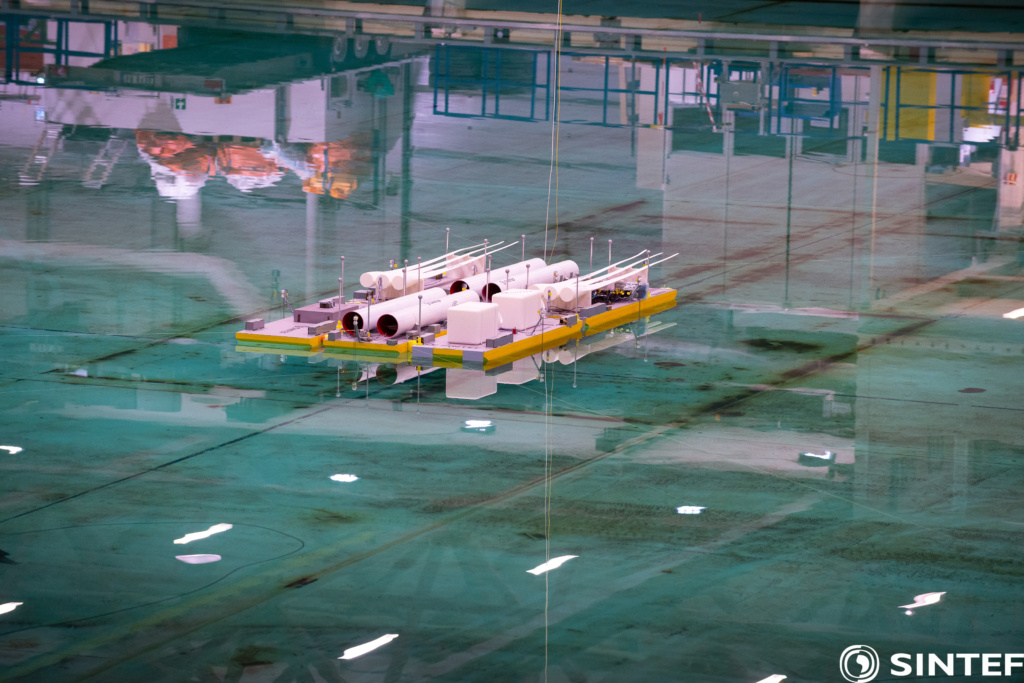
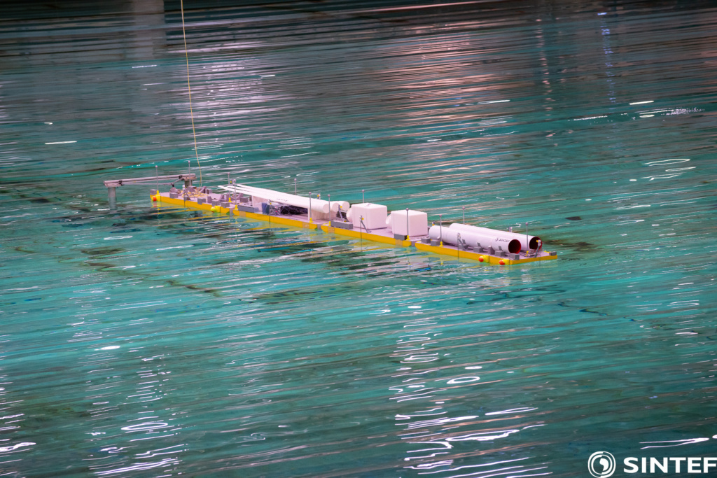
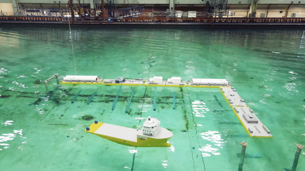
- A floating island (6 barges in a 2×3 arrangement)
- A floating deep-water pier (4 barges connected end-to-end) This is the set-up that was used for the numerical validation.
- A floating deep-water pier/harbour (6 barges connected in an L-shape arrangement)
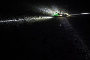
The images show pictures of the different configurations with models for 15 MW wind turbine components fixed on top. The model tests included decay and pull-out tests as well as tests in irregular waves. One of the main objectives of these tests was to provide guidance for validating and calibrating numerical models.
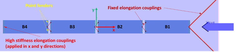
An important issue to address is the significance of hydrodynamic interactions between the barges. This is what we attempt to explore here, by modelling the (1×4) configuration in SIMA (a software developed by SINTEF Ocean for simulating marine operations and floating systems) and comparing the motion response estimates in irregular waves to the experimental results. In this configuration, the barges were connected end-to-end using fender and hawser connections (tennis balls were used as fenders). One of the two end barges was fixed horizontally while the other was attached to two fixed points to the side of the basin using mooring lines consisting of chain and spring assembly.
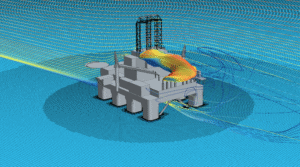
Each barge is modelled as a 6 degrees-of-freedom body in SIMA with its own structural and hydrodynamic properties. Figure 4 shows a top view of the setup of the numerical model in SIMA. Only unidirectional irregular waves in the negative x-direction (as shown in the figure below) are considered here.
The fender/hawser connections between the barges are modelled using “Point fenders” and “Fixed elongation” couplings available in SIMA. Point fenders give compressive forces parallel to the fender axis based on a force-distance relationship, while fixed elongation couplings are spring elements with specified length-force relation. In this implementation, a linear relationship between the force and distance/length is used for both coupling types. Fixed elongation couplings are also used to model the two mooring lines connected to barge number 1 as linear springs, as well as to fix barge number 4 horizontally by applying high stiffness values in both surge and sway directions.
Hydrodynamic modelling
The hydrodynamic loads on the barges are modelled based on potential flow theory using the boundary element method solver WAMIT. In order to investigate the effects of hydrodynamic coupling between the barges, two approaches are used to represent hydrodynamic loads in SIMA as follows:
- A decoupled approach in which the hydrodynamic coefficients are obtained based on a single-body boundary value problem (BVP) solution and applied to all barges ignoring interaction effects.
- A coupled approach which considers the effects of interaction between the barges by solving the multi-body BVP, and applies different hydrodynamic coefficients for each individual barge, as well as the coupling added inertia and radiation damping coefficients to model the loads acting on one barge due to the motions of another barge.
The single-body hydrodynamic problem (the decoupled approach)
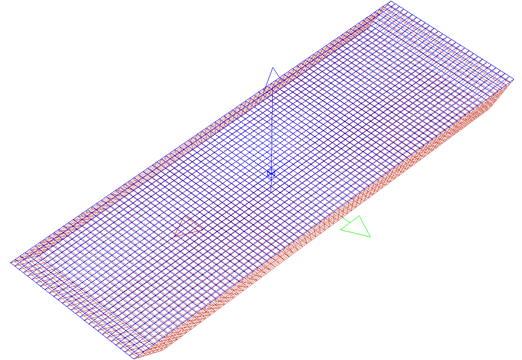
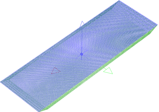
Two meshes were used in solving the single barge BVP, a coarse mesh (5932 panels) and a fine mesh (21228 panels) shown below in Figures 5 and 6, respectively. WAMIT allows for irregular frequencies removal by adding a surface lid (as shown by the blue panels in the figures). To investigate the sensitivity of the hydrodynamic coefficients to the mesh size and irregular frequencies, four solutions were obtained using both meshes with and without irregular frequencies removal.
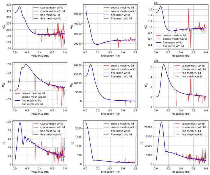
Surge, heave, and pitch normalised hydrodynamic added inertia, damping, and excitation amplitudes for the four solutions are compared in Figure 7. At low frequencies (below 0.3 Hz) all solutions give the same coefficients. On the other hand, at high frequencies, sharp discontinuities in the coefficients can be seen, especially for surge and pitch. The trends in the figure indicate that these discontinuities are caused by two reasons, namely, using a coarse mesh and irregular frequencies.
High frequency waves with short wavelengths require a finer mesh resolution to be able to capture the variation of hydrodynamic pressure along the barge’s shallow draft, this is why surge seems to be affected the most by this (this can be seen by comparing the solid blue and red curves). Additionally, irregular frequencies removal is also important for obtaining smooth solutions to the BVP (this is evidenced by the difference between the solid and dotted blue lines).
The multi-body hydrodynamic problem (the coupled approach)
For the multi-body BVP, four copies of the coarse mesh in Figure 6 (without the surface lid panels) are positioned similar to Figure 4 to create the mesh. It should be noted that the coarse mesh is used for solving the multi-body problem without irregular frequencies removal. This is due to the large computational expense (both in terms of processing time and memory) required to solve the problem for the fine mesh with irregular frequencies removal. Therefore, we emphasize that these results are merely to show the effect of hydrodynamic interactions between the bodies by comparing the solution to that of the corresponding single-body problem.
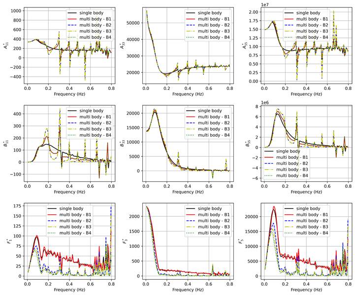
Figure 8 shows a comparison between the single and the multi-body hydrodynamic coefficients. As expected, sharp discontinuities (especially for surge and pitch) occur at frequencies higher than 0.2 Hz, which are likely a consequence of the coarse mesh and the irregular frequencies. Moreover, some frequencies have negative damping which is of course unphysical.
However, looking at the general trends, it seems that the effect of the presence of multiple bodies on added inertia and damping is less significant for heave and pitch compared to surge. However, for excitation, the effect of the presence of the multiple bodies in the diffraction problem can be clearly seen, where the upstream body (B1) has similar excitation coefficient to the single-body problem, while the “sheltered” bodies downstream have lower excitation forces at frequencies higher than 0.05 Hz.
Numerical vs. experimental motion responses
The hydrodynamic models presented above are now implemented in SIMA to compare the response estimates obtained numerically to the experimental results. Specifically, the coefficients from the fine mesh single-body solution with irregular frequencies removal is used for the decoupled approach, while the coupled approach uses the multi-body solution which employs the coarse mesh without irregular frequencies removal. In the experimental campaign, the model was tested in three wave conditions with head waves (as shown in Figure 4), these conditions are summarised in the table below.
Selected experimental tests
| Test ID | Type | Peak period | Significant Wave height | Figures |
| 3010 | Pink noise | 5-18 s | 1.5 m | 9-11 |
| 3020 | JONSWAP | 14.7 s | 0.46 m | 12-14 |
| 3031 | JONSWAP | 6.5 s | 1.5 m | 15-17 |
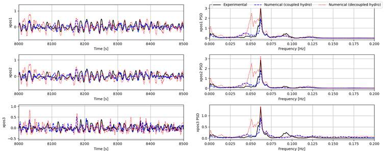
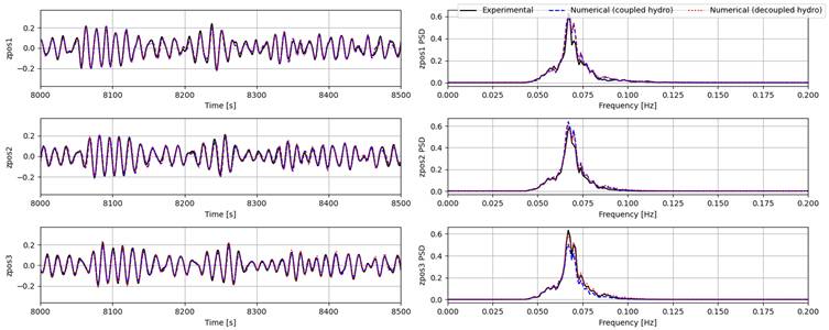
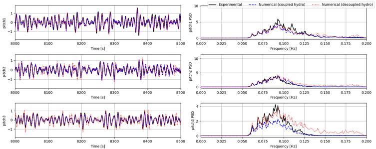
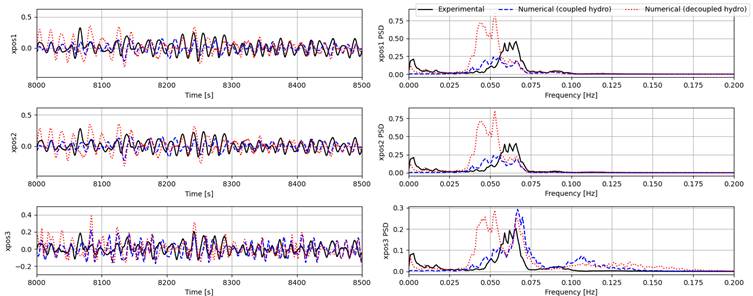
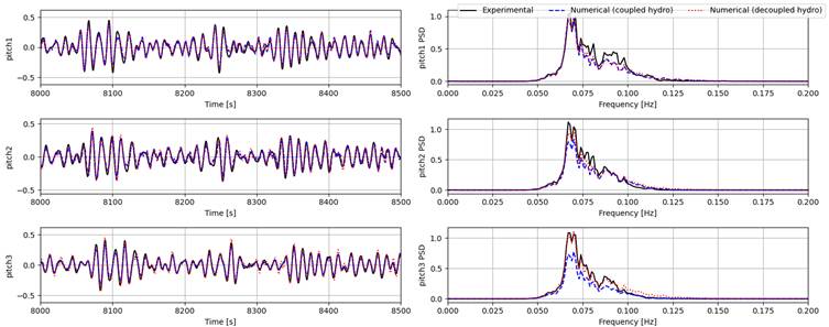
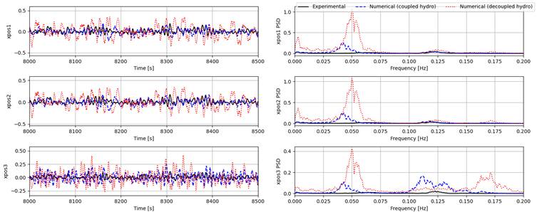
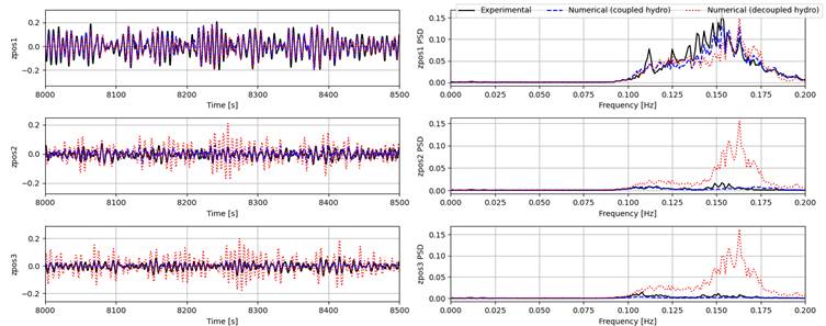
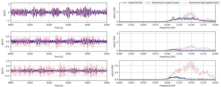
The time series of the surge, heave, and pitch responses of bodies 1 to 3 (body 4 is fixed horizontally and is not shown in the figures) and their power spectral densities (PSDs) from experiment and both the coupled and decoupled numerical models are given for each condition as summarized in the table above. It is important to point out that some nonlinear physical effects (such as viscous effects and second order pressure loads) are not modelled in the numerical setup, thus we only focus on first order responses in the following comparisons.
Generally, the coupled model gives much better estimates for surge responses for all tests compared to the decoupled model. Heave and pitch are captured quite well by both numerical models for the pink noise (Test 3010) and the high-period irregular wave (Test 3020). However, for the low-period wave (Test 3031), both models seem to largely overestimate surge response for all bodies. For heave and pitch, the coupled model can still provide good estimates, while the estimates of the decoupled model can only capture body 1 responses and overestimating the responses of bodies 2 and 3, showing the effect of the lower excitation forces experienced by the downstream bodies at higher frequencies. One possible reason for the discrepancies in surge can be the coarse mesh used for obtaining the hydrodynamic coefficients in the coupled model.
Conclusion
The results clearly show the need for modelling multi-body hydrodynamic coupling to be able to obtain accurate estimates of FOWYs. Furthermore, a finer mesh with irregular frequency removal should be employed in solving the multi-body BVP in WAMIT in order to get better coefficients and hence better response estimates. This requires significantly larger computational expenses both in terms of processing time and memory.


Comments
No comments yet. Be the first to comment!